
ProLiant BL p-Class C-GbE2 Interconnect Kit Quick Setup Instructions

Installation guidelines
Observe the following guidelines during installation:
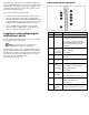
• Always install interconnect switches in pairs. Each server
blade enclosure requires two interconnect switches for
proper connectivity.
• Always install the interconnect modules into the bottom
left-most and bottom right-most bays on the rear side of
the server blade enclosure.
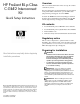
• Be sure that each interconnect module is firmly seated.
The latch or handle will drop into place when the module
is firmly seated.
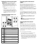
• Always install the interconnect switches into the
interconnect bays, which are the left-most (side A) and
right-most (side B) bays on the front side of the server
blade enclosure.
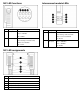
Installing the interconnect
switches and interconnect
modules
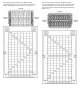
Planning the interconnect switch
configuration
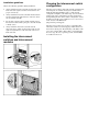
The interconnect switches ship with a default configuration in
which all ports are enabled and assigned a default virtual
LAN (VLAN) with VLAN ID equal to 1. This default
configuration simplifies your initial setup. Your environment
might require other configurations. For more information
about planning the interconnect switch configuration, refer to
the HP ProLiant BL p-Class GbE2 Interconnect Switch User
Guide located on the HP website
(http://www.hp.com/support).
The interconnect switch does not affect or determine NIC
numeration and the associated mapping of NIC interfaces to
interconnect switch ports. The numbering of the NICs on the
server (for example, NIC 1, NIC 2, NIC 3) is determined by
the server type, the server operating system, and what NICs
are enabled on the server.