
ProLiant BL p-Class C-GbE2 Interconnect Kit Quick Setup Instructions

Cabling the interconnect switch
IMPORTANT: If you are replacing an existing
ProLiant BL p-Class GbE2 Interconnect Switch or
upgrading from a ProLiant BL p-Class GbE Interconnect
Switch, a ProLiant BL p-Class RJ-45 Patch Panel, or a
ProLiant BL p-Class RJ-45 Patch Panel 2 and have strict
security requirements, you can perform one of the
following:
• Do not cable the interconnect switch until after
configuration.
• Connect the interconnect switch to the Diagnostic
Station. The Diagnostic Station enables you to power
up, configure, and diagnose a ProLiant p-Class
server blade or an interconnect switch outside of the
setup and installation guide for the server blade
enclosure.
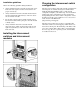
Connecting the network cables to the
interconnect modules
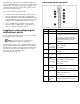
Item Description
1 Port 22 RJ-45 connector for 10/100/1000 Mb uplink for
Switch B
2 Port 21 RJ-45 connector for 10/100/1000 Mb uplink for
Switch B
3 Port 20 RJ-45 connector for 10/100/1000 Mb uplink for
Switch B
4 Port 19 RJ-45 connector for 10/100/1000 Mb uplink for
Switch B
5 Port 22 RJ-45 connector for 10/100/1000 Mb uplink for
Switch A
6 Port 21 RJ-45 connector for 10/100/1000 Mb uplink for
Switch A
7 Port 20 RJ-45 connector for 10/100/1000 Mb uplink for
Switch A
8 Port 19 RJ-45 connector for 10/100/1000 Mb uplink for
Switch A
Powering up the interconnect
switch
If the server blade enclosure has power applied, the
interconnect switch automatically begins to power up when
installed. The power status LED on the front of the
interconnect switch illuminates amber to indicate that power
is connected to the interconnect switch. After 30 seconds, the
power status LED turns to green to indicate that the
interconnect switch is on. After the built-in self-test flashes all
LEDs, the active links illuminate and the power status LED
stays green.
You can manually force the interconnect switch to power up
by pressing the Pwr/Rst button through the access hole in the
front panel of the interconnect switch, while the power status
LED is amber. HP recommends using a small, blunt object for
this purpose.
CAUTION: Pressing the Pwr/Rst button while the
power status LED is green will reset the interconnect
switch.
NOTE: If the server blade enclosure does not have
power applied, refer to the setup and installation guide
for the server blade enclosure.
Accessing the interconnect
switch
The interconnect switch can be accessed locally using the
front panel DB-9 serial management port or remotely using
either the 1000SX uplink Ethernet ports in the interconnect
module or the interconnect switch front panel Ethernet ports.
To access the interconnect switch remotely, you must assign
it an IP address. By default, the interconnect switch is set up
to obtain its IP address from a BOOTP server existing on the
attached network.
To access the interconnect switch remotely:
1. From the BOOTP server, use the interconnect switch
MAC address to obtain the switch IP address.
2. From a computer connected to the same network, use the
IP address to access the interconnect switch using a Web
browser or telnet application, which enables you to access
the interconnect switch browser-based interface (BBI) or
command line interface (CLI). The interconnect switch
logon prompt appears.