
ProLiant BL p-Class C-GbE2 Interconnect Kit Quick Setup Instructions

If the interconnect switch does not obtain the IP address by
means of the BOOTP service, you can access the interconnect
switch locally and configure the IP address manually. After
assigning the IP address to the interconnect switch, you can
then access the switch remotely.
To access the interconnect switch locally:
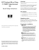
1. Connect the interconnect switch DB-9 serial connector,
using the null-modem serial cable (provided with the
following option kits: Scalable Busbar, Mini Busbar, and
Power Bus Box), to a local client device (such as a laptop
computer) with VT100 terminal emulation software.
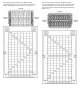
2. Open a VT100 terminal emulation session with the
following settings: 9600 baud rate, eight data bits, no
parity, one stop bit, and no flow control.
Logging on and configuring the
interconnect switch
To log on to the interconnect switch, enter admin for both
the default user name and password.
NOTE: If you are in the CLI, you might need to
press the Enter key to display the login prompt.
The interconnect switch comes configured with the factory
default configuration. For more information on configuring
the interconnect switch for your network environment, refer
to the HP ProLiant BL p-Class GbE2 Interconnect Switch
User Guide located on the HP website
(http://www.hp.com/support).
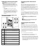
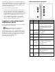
Interconnect switch front panel
Item Description Status/function
1 10G LED Reserved for future use.
2 SAN LED Off = HP ProLiant BL p-Class GbE2
Storage Connectivity Kit is not installed.
On = Refer to the HP ProLiant BL
p-Class GbE2 Storage Connectivity Kit
Quick Setup Instructions for more
information.
3 Front panel
RJ-45
connector link
speed LEDs
Amber = 1000 Mb/s
Green = 100 Mb/s
Off = 10 Mb/s
4 Pwr/Rst button Forces the interconnect switch to power
up or reboot.
5 DB-9
connector
Used to access the local management
console.
6 Front panel
RJ-45
connector link
activity LEDs
Green = Link and no activity
Green flashing = Link and activity
Amber = Port disabled
Off = No link
7 Management
status LED
Flashing = Management session active
Off = No management session active
8 Power status
LED
Green = Power on
Amber = Stand-by mode
Off = Power off
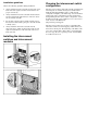
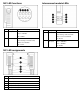
9 Link activity
and speed
LEDs
Refer to the following figures and tables
for LED assignments and functions.