HP ProLiant BL p-Class GbE2 Interconnect Switch Application Guide Part number: 331403-008 Eighth edition: March 2007
Legal notices © 2004, 2007 Hewlett-Packard Development Company, L.P. The information contained herein is subject to change without notice. The only warranties for HP products and services are set forth in the express warranty statements accompanying such products and services. Nothing herein should be construed as constituting an additional warranty. HP shall not be liable for technical or editorial errors or omissions contained herein. Microsoft®, Windows®, and Windows NT® are U.S.
Contents Accessing the GbE2 Interconnect Switch Introduction ............................................................................................................................................. 8 Additional references ............................................................................................................................... 8 Typographical conventions........................................................................................................................
Supported RADIUS attributes .............................................................................................................. 42 EAPoL configuration guidelines ........................................................................................................... 43 Port-based traffic control ......................................................................................................................... 43 VLANs Introduction .......................................................
MSTP configuration guidelines ............................................................................................................ 68 MSTP configuration example .............................................................................................................. 68 Quality of Service Introduction ........................................................................................................................................... 73 Overview............................................
OSPF OSPF overview .................................................................................................................................... 111 Types of OSPF areas ....................................................................................................................... 111 Types of OSPF routing devices.......................................................................................................... 112 Neighbors and adjacencies .............................................
Troubleshooting tools Introduction ......................................................................................................................................... 163 Port Mirroring...................................................................................................................................... 163 Configuring Port Mirroring (CLI example) ........................................................................................... 164 Configuring Port Mirroring (BBI example) ...
Accessing the GbE2 Interconnect Switch Introduction This guide will help you plan, implement, and administer the HP ProLiant BL p-Class GbE2 Interconnect Switch software. Where possible, each section provides feature overviews, usage examples, and configuration instructions. • “Accessing the GbE2 Interconnect Switch” describes how to configure and view information and statistics on the GbE2 Interconnect Switch over an IP network.
Typographical conventions The following table describes the typographic styles used in this guide: Table 1 Typographic conventions Typeface or symbol Meaning Example AaBbCc123 This type depicts onscreen computer output and prompts. Main# AaBbCc123 This type displays in command examples and Main# sys shows text that must be typed in exactly as shown. This italicized type displays in command examples as a parameter placeholder.
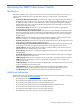
The following example shows how to manually configure an IP address on the GbE2 Interconnect Switch: 1. Configure an IP interface for the Telnet connection, using the sample IP address of 205.21.17.3. 2. The pending subnet mask address and broadcast address are automatically calculated. >> # /cfg/l3/if 1 (Select IP interface 1) >> IP Interface 1# addr 205.21.17.3 (Assign IP address for the interface) Current IP address: 0.0.0.0 New pending IP address: 205.21.17.3 Pending new subnet mask: 255.255.
The BBI is organized at a high level as follows: • Configuration—These menus provide access to the configuration elements for the entire switch. • System—Configure general switch configuration elements. • Switch Ports—configure switch ports and related features. • Port-Based Port Mirroring—Configure mirrored ports and monitoring ports. • Layer 2—Configure Layer 2 features, including Trunk Groups, VLANs, and Spanning Tree Protocol. • RMON Menu—Configure Remote Monitoring (RMON) functions.
Default configuration GbE2 software has two users by default. Both the users 'adminmd5' and 'adminsha' have access to all the MIBs supported by the switch. 1. username 1: adminmd5/password adminmd5. Authentication used is MD5. 2. username 2 adminsha/password adminsha. Authentication used is SHA. 3. username 3 v1v2only/password none.
View based configurations CLI user equivalent To configure an SNMP user equivalent to the CLI 'user,' use the following configuration: /c/sys/ssnmp/snmpv3/usm 4 name "usr" /c/sys/ssnmp/snmpv3/access 3 name "usrgrp" rview "usr" wview "usr" nview "usr" /c/sys/ssnmp/snmpv3/group 4 uname usr gname usrgrp /c/sys/ssnmp/snmpv3/view 6 name "usr" tree " 1.3.6.1.4.1.11.2.3.7.11.33.1.2.1.2" /c/sys/ssnmp/snmpv3/view 7 name "usr" tree " 1.3.6.1.4.1.11.2.3.7.11.33.1.2.1.3" /c/sys/ssnmp/snmpv3/view 8 name "usr" tree " 1.
Configuring SNMP trap hosts SNMPv1 trap host 1. Configure a user with no authentication and password. /c/sys/ssnmp/snmpv3/usm 10 name "v1trap" 2. Configure an access group and group table entries for the user. The command /c/sys/ssnmp/snmpv3/access /nview can be used to specify which traps can be received by the user. In the example below the user will receive the traps sent by the switch.
SNMPv2 trap host configuration The SNMPv2 trap host configuration is similar to the SNMPv1 trap host configuration. Wherever you specify the model you need to specify snmpv2 instead of snmpv1. c/sys/ssnmp/snmpv3/usm 10 name "v2trap" /c/sys/ssnmp/snmpv3/access 10 name "v2trap" model snmpv2 nview "iso" /c/sys/ssnmp/snmpv3/group 10 model snmpv2 uname v2trap gname v2trap /c/sys/ssnmp/snmpv3/taddr 10 name v2trap addr 47.81.25.
Secure access to the switch Secure switch management is needed for environments that perform significant management functions across the Internet. The following are some of the functions for secured management: • Limiting management users to a specific IP address range. See the “Setting allowable source IP address ranges” section in this chapter. • Authentication and authorization of remote administrators.
The GbE2 Interconnect Switch, acting as the RADIUS client, communicates to the RADIUS server to authenticate and authorize a remote administrator using the protocol definitions specified in RFC 2138 and 2866. Transactions between the client and the RADIUS server are authenticated using a shared key that is not sent over the network. In addition, the remote administrator passwords are sent encrypted between the RADIUS client (the switch) and the back-end RADIUS server.
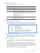
4. Configure the number of retry attempts for contacting the RADIUS server, and the timeout period. >> RADIUS Server# retries Current RADIUS server retries: 3 Enter new RADIUS server retries [1-3]: >> RADIUS Server# time Current RADIUS server timeout: 3 Enter new RADIUS server timeout [1-10]: 10 (Enter the timeout period in seconds) Configuring RADIUS on the switch (BBI example) 1. Configure RADIUS parameters. a. Click the Configure context button. b.
c. Enter the IP address of the primary and secondary RADIUS servers, and enter the RADIUS secret for each server. Enable the RADIUS server. CAUTION: If you configure the RADIUS secret using any method other than a direct console connection, the secret may be transmitted over the network as clear text. d. Click Submit. 2. Apply, verify, and save the configuration.
• Allows network administrator to define privileges for one or more specific users to access the GbE2 Interconnect Switch at the RADIUS user database. • Allows the administrator to configure RADIUS backdoor and secure backdoor for Telnet, SSH, HTTP, and HTTPS access. User accounts for RADIUS users The user accounts listed in the following table can be defined in the RADIUS server dictionary file.
TACACS+ authentication GbE2 software supports authentication, authorization, and accounting with networks using the Cisco Systems TACACS+ protocol. The HP ProLiant BL p-Class GbE2 Interconnect Switch functions as the Network Access Server (NAS) by interacting with the remote client and initiating authentication and authorization sessions with the TACACS+ access server.
Alternate mapping between TACACS+ privilege levels and GbE2 management access levels is shown in the table below. Use the command /cfg/sys/tacacs/cmap ena to use the alternate TACACS+ privilege levels. Table 5 Alternate TACACS+ privilege levels User access level TACACS+ level user 0-1 oper 6-8 admin 14 - 15 You can customize the mapping between TACACS+ privilege levels and GbE2 management access levels.
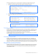
2. Configure the TACACS+ secret and second secret. >> TACACS+ Server# secret Enter new TACACS+ secret: <1-32 character secret> >> TACACS+ Server# secret2 Enter new TACACS+ second secret: <1-32 character secret> CAUTION: If you configure the TACACS+ secret using any method other than a direct console connection, the secret may be transmitted over the network as clear text. 3. If desired, you may change the default TCP port number used to listen to TACACS+. 4. The well-known port for TACACS+ is 49.
Configuring TACACS+ authentication on the switch (BBI example) 1. Configure TACACS+ authentication for the switch. a. Click the Configure context button. b. Open the System folder, and select Tacacs+. c. Enter the IP address of the primary and secondary TACACS+ servers, and enter the TACACS+ secret. Enable TACACS+. d. Click Submit.
e. Configure custom privilege-level mapping (optional). Click Submit to accept each mapping change. 2. Apply, verify, and save the configuration. Secure Shell and Secure Copy Secure Shell (SSH) and Secure Copy (SCP) use secure tunnels to encrypt and secure messages between a remote administrator and the GbE2 Interconnect Switch. Telnet does not provide this level of security. The Telnet method of managing a GbE2 Interconnect Switch does not provide a secure connection.
Configuring SSH and SCP features (CLI example) Before you can use SSH commands, use the following commands to turn on SSH and SCP. Enabling or disabling SSH To enable or disable the SSH feature, connect to the GbE2 Interconnect Switch CLI and enter the following commands: >> # /cfg/sys/sshd/on (Turn SSH on) Current status: OFF New status: ON >> # /cfg/sys/sshd/off (Turn SSH off) Current status: OFF New status: ON NOTE: Secure Shell can be configured using the console port only.
Using SSH and SCP client commands The following shows the format for using some client commands. The examples below use 205.178.15.157 as the IP address of a sample GbE2 Interconnect Switch. Logging in to the GbE2 Interconnect Switch Enter the following command to log in to the GbE2 Interconnect Switch: ssh @ For example: >> # ssh admin@205.178.15.
SSH and SCP encryption of management messages The following encryption and authentication methods are supported for SSH and SCP: • Server Host Authentication—Client RSA authenticates the switch at the beginning of every connection • Key Exchange—RSA • Encryption—AES256-CBC, AES192-CBC, 3DES-CBC, 3DES, ARCFOUR • User Authentication—Local password authentication, RADIUS, TACACS+ IMPORTANT: The SCP-only administrator password must be different from the regular administrator password.
User access control The GbE2 Interconnect Switch allows an administrator to define end user accounts that permit end users to perform limited actions on the switch. Once end user accounts are configured and enabled, the switch requires username/password authentication. For example, an administrator can assign a user who can log into the switch and perform operational commands (effective only until the next switch reboot).
Ports and trunking Introduction NOTE: All conceptual diagrams and port mappings in this chapter are based on BL 20p G3 servers. If you are using a next generation server, then see the latest Quick Setup Instructions card for correct port mappings. The first part of this chapter describes the different types of ports used on the GbE2 Interconnect Switch. This information is useful in understanding other applications described in this guide, from the context of the embedded switch/server environment.
Table 6 Ethernet switch port names Port number LED Port alias 21 P21 Uplink3 22 P22 Uplink4 23 P23 FrontPanel1 24 P24 FrontPanel2 Port trunk groups When using port trunk groups between two GbE2 Interconnect Switches, you can create an aggregate link operating at up to four Gigabits per second, depending on how many physical ports are combined. The GbE2 Interconnect Switch supports up to 12 trunk groups per switch, each with up to six ports per trunk group.
Trunk group configuration rules The trunking feature operates according to specific configuration rules. When creating trunks, consider the following rules that determine how a trunk group reacts in any network topology: • All trunks must originate from one device, and lead to one destination device. For example, you cannot combine a link from Server 1 and a link from Server 2 into one trunk group. • Any physical switch port can belong to only one trunk group.
Figure 1 Port trunk group configuration example The trunk groups are configured as follows: • Trunk group 1 is configured by default on the crosslink ports 17 and 18, which connect the GbE2 Interconnect Switches A and B together. Since this is the default configuration, you do not need to configure trunk group 1 on either GbE2 Interconnect Switch. • Trunk groups 2-5 consist of two Gigabit uplink ports each, configured to act as a single link to the upstream routers.
2.
c. Click a Trunk Group number to select it. d. Enable the Trunk Group. To add ports, select each port in the Ports Available list, and click Add. e. Click Submit.
2. Apply, verify, and save the configuration. 3. Examine the trunking information on each switch. a. Click the Dashboard context button on the Toolbar. b. Select Trunk Groups.
c. Information about each configured trunk group is displayed. Make sure that trunk groups consist of the expected ports and that each port is in the expected state. Configurable Trunk Hash algorithm This feature allows you to configure the particular parameters for the GbE2 Trunk Hash algorithm instead of having to utilize the defaults. You can configure new default behavior for Layer 2 traffic and Layer 3 traffic, using the CLI menu cfg/l2/thash.
For example, consider two switches, an Actor (the GbE2) and a Partner (another switch), as shown in the following table: Table 7 Actor vs.
5. Apply and verify the configuration. >> LACP port 20# apply >> LACP port 20# cur 6. (Make your changes active) (View current trunking configuration) Save your new configuration changes.
Port-based Network Access and traffic control Port-based Network Access control Port-based Network Access control provides a means of authenticating and authorizing devices attached to a LAN port that has point-to-point connection characteristics. It prevents access to ports that fail authentication and authorization. This feature provides security to all ports of the GbE2 Interconnect Switch. The following topics are discussed in this section: • Extensible Authentication Protocol over LAN • 802.
The following figure shows a typical message exchange initiated by the client. Figure 2 Using EAPoL to authenticate a port EAPoL Message Exchange During authentication, EAPOL messages are exchanged between the client and the switch authenticator, while RADIUS-EAP messages are exchanged between the switch authenticator and the Radius authentication server. Authentication is initiated by one of the following methods: Switch authenticator sends an EAP-Request/Identity packet to the client.
If a client that does not support 802.1x connects to an 802.1x-controlled port, the switch authenticator requests the client's identity when it detects a change in the operational state of the port. The client does not respond to the request, and the port remains in the unauthorized state. NOTE: When an 802.1x-enabled client connects to a port that is not 802.1x-controlled, the client initiates the authentication process by sending an EAPOL-Start frame.
Table 8 EAP support for RADIUS attributes # Attribute Attribute Value A-R A-A A-C A-R 31 Calling-Station-ID The MAC address of the supplicant encoded as an ASCII string in canonical format, e.g. 00034B436206. 1 0 0 0 79 EAP-Message Encapsulated EAP packets from the 1+ supplicant to the authentication server (Radius) and vice-versa. The authenticator relays the decoded packet to both devices.
Configuring port-based traffic control To configure a port for traffic control, perform the following steps: 1. Configure the traffic-control threshold and enable traffic control. Main# /cfg/port 2 >> Port 2# brate 150000 >> Port 2# mrate 150000 >> Port 2# drate 150000 2. To disable a traffic-control threshold, use the following command: >> Port 2# mrate dis 3. (Set broadcast threshold) (Set multicast threshold) (Set DLF threshold) Apply and save the configuration.
VLANs Introduction This chapter describes network design and topology considerations for using Virtual Local Area Networks (VLANs). VLANs are commonly used to split up groups of network users into manageable broadcast domains, to create logical segmentation of workgroups, and to enforce security policies among logical segments.
Viewing and configuring PVIDs You can view PVIDs from the following CLI commands: Port information >> /info/port Port Tag RMON PVID NAME VLAN(s) ---- --- ---- ---- -------------- ------------------------------1 n d 1 Downlink1 1 2 n e 1 Downlink2 1 3 n d 1 Downlink3 1 4 n d 1 Downlink4 1 5 n d 1 Downlink5 1 6 n d 1 Downlink6 1 7 n d 1 Downlink7 1 : : Port configuration >> /cfg/port 22/pvid 22 Current port VLAN ID: 1 New pending port VLAN ID: 22 >> Port 22# Each port on the GbE2 Interconnect Switch can bel
NOTE: If an 802.1Q tagged frame is sent to a port that has VLAN-tagging disabled, then the frames are forwarded based on their port-VLAN ID (PVID). Figure 3 Default VLAN settings NOTE: The port numbers specified in these illustrations may not directly correspond to the physical port configuration of your GbE2 Interconnect Switch model. When you configure VLANs, you configure the GbE2 Interconnect Switch ports as tagged or untagged members of specific VLANs. Refer to the following figures.
Figure 5 802.1Q tagging (after port-based VLAN assignment) In the following figure, the tagged incoming packet is assigned directly to VLAN 2 because of the tag assignment in the packet. Port 5 is configured as a tagged member of VLAN 2, and port 7 is configured as an untagged member of VLAN 2. Figure 6 802.1Q tag assignment As shown in the following figure, the tagged packet remains unchanged as it leaves the GbE2 Interconnect Switch through port 5, which is configured as a tagged member of VLAN 2.
VLANs and IP interfaces Carefully consider how you create VLANs within the GbE2 Interconnect Switch, so that communication with the GbE2 Interconnect Switch remains possible. In order to access the GbE2 Interconnect Switch for remote configuration, trap messages, and other management functions, make sure that at least one IP interface on the GbE2 Interconnect Switch has a VLAN defined. You can also inadvertently cut off access to management functions if you exclude the ports from the VLAN membership.
Figure 8 Multiple VLANs with VLAN tagging The features of this VLAN are described in the following table: Table 9 Multiple VLANs with tagging Component Description Switch A Switch A is configured for VLANS 1, 2, and 3. Port 1 is tagged to accept traffic from VLANs 1 and 2. Ports 17 and 18 are tagged members of a trunk that accepts traffic from VLANs 1 and 3. Port 20 is tagged to accept traffic from VLANs 1, 2, and 3. Port 23 is an untagged member of VLAN 2.
Table 9 Multiple VLANs with tagging Component Description PC #4 This PC is a member of VLAN 3, and it can communicate with Server 1, Server 2, and PC 1. PC #5 This PC is a member of both VLAN 1 and VLAN 2. Via VLAN 1, it can communicate with Server 1 and PC 3. Via VLAN 2, it can communicate with Server 1, PC 1, and PC 3. The Layer 2 switch port to which it is connected is configured for both VLAN 1 and VLAN 2 and has tagging enabled.
2. Configure the VLANs and their member ports. Since all ports are by default configured for VLAN 1, configure only those ports that belong to VLAN 2. crosslink ports 17 and 18 must belong to VLANs 1 and 2.
2. Configure the VLANs and their member ports. Since all ports are by default configured for VLAN 1, configure only those ports that belong to other VLANs.
c. Click a port number to select it. d. Enable the port and enable VLAN tagging. e. Click Submit.
2. Configure the VLANs and their member ports. a. Open the Virtual LANs folder, and select Add VLAN. b. Enter the VLAN name, VLAN ID number, and enable the VLAN. To add ports, select each port in the Ports Available list and click Add. Since all ports are configured for VLAN 1 by default, configure only those ports that belong to VLAN 2. The crosslink ports 17 and 18 must belong to VLANs 1 and 2. c. Click Submit.
3. Apply, verify, and save the configuration. The external Layer 2 switches should also be configured for VLANs and tagging. FDB static entries Static entries in the Forwarding Database (FDB) allow the switch to forward packets without flooding ports to perform a lookup. A FDB static entry is a MAC address associated with a specific port and VLAN. The GbE2 supports 128 static entries. Static entries are manually configured, using the /cfg/l2/fdb/static command.
Spanning Tree Protocol Introduction When multiple paths exist on a network, Spanning Tree Protocol (STP) configures the network so that a switch uses only the most efficient path. The following topics are discussed in this chapter: • Overview • Bridge Protocol Data Units (BPDUs) • Spanning Tree Group (STG) configuration guidelines • Multiple Spanning Trees Overview Spanning Tree Protocol (STP) detects and eliminates logical loops in a bridged or switched network.
Port path cost The port path cost assigns lower values to high-bandwidth ports, such as Gigabit Ethernet, to encourage their use. The objective is to use the fastest links so that the route with the lowest cost is chosen. A value of 0 indicates that port cost is computed dynamically based on link speed. This works when forcing link speed, so it does not just apply to “auto negotiated link speed”. By default, all switch ports have the path cost set to 4, independent of the link speed.
Adding and removing ports from STGs Information on adding and removing ports from STGs is as follows: • By default, all ports belong to VLAN 1 and STG 1. • Each port is always a member of at least one VLAN. Each VLAN is always a member of at least one STG. Port membership within VLANs can be changed, and VLAN membership within STGs can be changed. To move a port from one STG to another, move the VLAN to which the port belongs, or move the port to a VLAN that belongs to the STG.
Figure 9 Two VLANs on one instance of Spanning Tree Protocol In the following figure, VLAN 1 and VLAN 2 belong to different Spanning Tree Groups. The two instances of spanning tree separate the topology without forming a loop, so that both VLANs can forward packets between the switches without losing connectivity.
Configuring Switch A (CLI example) 1. Configure port and VLAN membership on Switch A as described in the “Configuring Ports and VLANs on Switch A (CLI example)” section, in the “VLANs” chapter of this guide. 2. Add VLAN 2 to Spanning Tree Group 2. >> /cfg/l2/stp 2 >> Spanning Tree Group 2# add 2 (Select Spanning Tree Group 2) (Add VLAN 2) VLAN 2 is automatically removed from spanning tree group 1. 3. Apply and save.
c. Enter the Spanning Tree Group number and set the Switch Spanning Tree State to on. To add a VLAN to the Spanning Tree Group, select the VLAN in the VLANs Available list, and click Add. VLAN 2 is automatically removed from Spanning Tree Group 1. d. Scroll down, and click Submit. 3. Apply, verify, and save the configuration.
Configuring Port Fast Forwarding Use the following CLI commands to enable Port Fast Forwarding on an external port.
Pre-emption You can configure the Master interface to resume the active state whenever it becomes available. With Hot Links pre-emption enabled (/cfg/l2/hotlink/trigger x/preempt ena), the Master interface transitions to the active state immediately upon recovery. The Backup interface immediately transitions to the standby state. If Forward Delay is enabled, the transition occurs when an interface has maintained link stability for the duration of the Forward Delay period.
RSTP and MSTP Introduction Rapid Spanning Tree Protocol (IEEE 802.1w) enhances the Spanning Tree Protocol (IEEE 802.1d) to provide rapid convergence on Spanning Tree Group 1. Multiple Spanning Tree Protocol (IEEE 802.1s) extends the Rapid Spanning Tree Protocol to provide both rapid convergence and load balancing in a VLAN environment.
Link type The link type determines how the port behaves in regard to Rapid Spanning Tree. The link type corresponds to the duplex mode of the port. A full-duplex link is point-to-point (p2p), while a half-duplex link should be configured as shared. If you select auto as the link type, the port dynamically configures the link type.
3. Configure RSTP general parameters. a. Click the Configure context button on the Toolbar. b. Open the MSTP/RSTP folder, and select General. c. Select RSTP mode, and set the MSTP/RSTP state to ON. d. Click Submit. 4. Apply, verify, and save the configuration.
Multiple Spanning Tree Protocol IEEE 802.1s Multiple Spanning Tree extends the IEEE 802.1w Rapid Spanning Tree Protocol through multiple Spanning Tree Groups. MSTP maintains up to 32 spanning-tree instances that correspond to STP Groups 1-32. In Multiple Spanning Tree Protocol (MSTP), several VLANs can be mapped to each Spanning-Tree instance. Each Spanning-Tree instance is independent of other instances.
Configuring Multiple Spanning Tree Protocol (CLI example) 1. Configure port and VLAN membership on the switch, as described in the “Configuring Ports and VLANs (CLI example)” section in the “VLANs” chapter of this guide. 2. Set the mode to Multiple Spanning Tree, and configure MSTP region parameters.
c. Enter the region name and revision level. Select MSTP mode, and set the MSTP/RSTP state to ON. d. Click Submit. 3. Configure Common Internal Spanning Trees (CIST) bridge parameters. a. Open the MSTP/RSTP folder, and select CIST-Bridge.
b. Change the Bridge Priority, Maximum Age, and Forward Delay values, if necessary. c. 4. Click Submit. Configure Common Internal Spanning Tree (CIST) port parameters. a. Open the MSTP/RSTP folder, and select CIST-Ports.
b. Click a port number to select it. c. Enter the Port Priority, Path Cost, and select the Link Type. Set the CIST Port State to ON. d. Click Submit. 5. Apply, verify, and save the configuration.
Quality of Service Introduction Quality of Service features allow you to allocate network resources to mission-critical applications at the expense of applications that are less sensitive to such factors as time delays or network congestion. You can configure your network to prioritize specific types of traffic, ensuring that each type receives the appropriate Quality of Service (QoS) level.
• • Perform actions: • Drop packets • Pass packets • Mark DSCP or 802.1p Priority • Set COS queue (with or without re-marking) Queue and schedule traffic: • Place packets in one of eight COS queues • Schedule transmission based on the COS queue weight Using ACL filters Access Control Lists are filters that allow you to classify and segment traffic, so you can provide different levels of service to different traffic types.
Table 14 Well-known application ports Number TCP/UDP Application Number TCP/UDP Application Number TCP/UDP Application 37 time 119 nntp 520 rtsp 42 name 123 ntp 554 Radius 43 whois 143 imap 1645, 1812 Radius Accounting 53 domain 144 news 1813 hsrp 69 tftp 161 snmp 1985 70 gopher 162 snmptrap Table 15 Well-known TCP flag values Flag Value URG 0x0020 ACK 0x0010 PSH 0x0008 RST 0x0004 SYN 0x0002 FIN 0x0001 • • Packet Format • Ethernet format (eth2, 802.
ACLs can be grouped in the following manner: • Access Control Lists Access Control Lists (ACLs) allow you to classify packets according to a particular content in the packet header, such as the source address, destination address, source port number, destination port number, and others. Packet classifiers identify flows for more processing. The GbE2 supports up to 4096 ACLs. Each ACL defines one filter rule.
Port-Based QoS actions You can define a profile for the aggregate traffic flowing through the GbE2, by assigning an ACL Group to the port and configuring a QoS meter (if desired). When you add ACL Groups to a port, make sure they are ordered correctly in terms of precedence. For example, consider two ACL Groups, ACL Group 1 and ACL Group 2. Each contains three levels of precedence.
ACL configuration examples Configure Access Control Lists (CLI example) The following configuration examples illustrate how to use Access Control Lists (ACLs) to block traffic. These basic configurations illustrate common principles of ACL filtering. NOTE: Each ACL filters traffic that ingresses on the port to which the ACL is added. The egrport classifier filters traffic that ingresses the port to which the ACL is added, and then egresses the port specified by egrport.
Configure Access Control Lists and Groups (BBI example 1) 1. Configure Access Control Lists (ACLs). a. Click the Configure context button on the Toolbar. b. Open the Access Control Lists folder, and select Add ACL.
c. Configure the ACL parameters. Set the Filter Action to Deny, the Ethernet Type to IPv4, and the Destination IP Address to 100.10.1.116. d. Click Submit. 2. Apply, verify, and save the configuration.
3. Add ACL 1 to port 1. a. Click the Configure context button on the Toolbar. b. Select Switch Ports (click the underlined text, not the folder). c. Select a port.
d. Add the ACL to the port. e. Click Submit. 4. Apply, verify, and save the configuration. Using DSCP values to provide QoS The six most significant bits in the TOS byte of the IP header are defined as DiffServ Code Points (DSCP). Packets are marked with a certain value depending on the type of treatment the packet must receive in the network device. DSCP is a measure of the Quality of Service (QoS) level of the packet.
Differentiated Services concepts To differentiate between traffic flows, packets can be classified by their DSCP value. The Differentiated Services (DS) field in the IP header is an octet, and the first six bits, called the DS Code Point (DSCP), can provide QoS functions. Each packet carries its own QoS state in the DSCP. There are 64 possible DSCP values (0-63).
Ingress packets receive a priority value, as follows: • Tagged packets—GbE2 reads the 802.1p priority in the VLAN tag. • Untagged packets—GbE2 tags the packet and assigns an 802.1p priority, based on the port’s default priority (/cfg/port x/8021ppri). Egress packets are placed in a COS queue based on the priority value, and scheduled for transmission based on the scheduling weight of the COS queue. Use the /cfg/qos/8021p/cur command to display the mapping between 802.
802.1p configuration (BBI example) 1. Configure a port’s default 802.1p priority. a. Click the Configure context button on the Toolbar. b. Select Switch Ports (click the underlined text, not the folder). c. Select a port.
d. Set the 802.1p priority value. e. Click Submit.
2. Map the 802.1p priority value to a COS queue. a. Click the Configure context button on the Toolbar. b. Open the 802.1p folder, and select Priority - CoS. c. Select an 802.1p priority value. d. Select a Class of Service queue (CoSQ) to correlate with the 802.1p priority value. e. Click Submit.
3. Set the COS queue scheduling weight. a. Click the Configure context button on the Toolbar. b. Open the 802.1p folder, and select CoS - Weight. c. Select a Class of Service queue (CoS). d. Enter a value for the weight of the Class of Service queue. e. Click Submit.
f. Apply, verify, and save the configuration. Queuing and scheduling The GbE2 has eight output Class of Service queues (COSq) per port (0-7), into which each packet is placed. Each packet’s 802.1p priority determines its COSq, except when an ACL action sets the COSq of the packet. Class Of Service queues 0 - 6 use Weighted Round Robin (WRR) scheduling, with user configurable weight from 1 to 15. The weight of 0 (zero) indicates strict priority, which might starve the low priority queues.
Basic IP routing This chapter provides configuration background and examples for using the GbE2 Interconnect Switch to perform IP routing functions. The following topics are addressed in this chapter: • IP Routing Benefits • Routing Between IP Subnets • Example of Subnet Routing • Defining IP Address Ranges for the Local Route Cache • Dynamic Host Configuration Protocol IP routing benefits The GbE2 Interconnect Switch uses a combination of configurable IP switch interfaces and IP routing options.
In this example, a corporate campus has migrated from a router-centric topology to a faster, more powerful, switch-based topology. As is often the case, the legacy of network growth and redesign has left the system with a mix of illogically distributed subnets. This is a situation that switching alone cannot cure. Instead, the router is flooded with cross-subnet communication. This compromises efficiency in two ways: • Routers can be slower than switches.
Example of subnet routing Prior to configuring, you must be connected to the switch Command Line Interface (CLI) as the administrator. NOTE: For details about accessing and using any of the menu commands described in this example, see the HP ProLiant BL p-Class GbE2 Interconnect Switch Command Reference Guide. 1. Assign an IP address (or document the existing one) for each router and client workstation.
4. Configure the default gateways to the routers’ addresses. Configuring the default gateways allows the switch to send outbound traffic to the routers: >> IP Interface 5# ../gw 1 (Select primary default gateway) >> Default gateway 1# addr 205.21.17.1(Assign IP address) >> Default gateway 1# ena (Enable primary default gateway) >> Default gateway 1# ../gw 2 (Select secondary default gateway) >> Default gateway 2# addr 205.21.17.2 (Assign address) >> Default gateway 2# ena 5.
2. Add the switch ports to their respective VLANs. The VLANs shown in the table above are configured as follows: >> # /cfg/l2/vlan 1(Select VLAN 1) >> VLAN 1# add port 19 (Add port for 1st floor to VLAN 1) >> VLAN 1# add port 20 (Add port for 2nd floor to VLAN 1) >> VLAN 1# ena (Enable VLAN 1) >> VLAN 1# ../VLAN 2 (Select VLAN 2) >> VLAN 2# add port 21 (Add port for default router 1) >> VLAN 2# add port 22 (Add port for default router 2) >> VLAN 2# ena (Enable VLAN 2) >> VLAN 2# ..
Dynamic Host Configuration Protocol Dynamic Host Configuration Protocol (DHCP) is a transport protocol that provides a framework for automatically assigning IP addresses and configuration information to other IP hosts or clients in a large TCP/IP network. Without DHCP, the IP address must be entered manually for each network device.
DHCP relay agent configuration To enable the switch to be the BOOTP forwarder, you need to configure the DHCP/BOOTP server IP addresses on the switch. Generally, you should configure the command on the switch IP interface closest to the client so that the DHCP server knows from which IP subnet the newly allocated IP address should come. The following figure shows a basic DHCP network example: Figure 16 DHCP relay agent configuration In GbE2 implementation, there is no need for primary or secondary servers.
Routing Information Protocol In a routed environment, routers communicate with one another to keep track of available routes. Routers can learn about available routes dynamically, using the Routing Information Protocol (RIP). GbE2 software supports RIP version 1 (RIPv1) and RIP version 2 (RIPv2) for exchanging TCP/IP route information with other routers. Distance vector protocol RIP is known as a distance vector protocol.
RIPv2 in RIPv1 compatibility mode GbE2 software allows you to configure RIPv2 in RIPv1compatibility mode, for using both RIPv2 and RIPv1 routers within a network. In this mode, the regular routing updates use broadcast UDP data packet to allow RIPv1 routers to receive those packets. With RIPv1 routers as recipients, the routing updates have to carry natural or host mask. Hence, it is not a recommended configuration for most network topologies.
RIP configuration example NOTE: An interface RIP disabled uses all the default values of the RIP, no matter how the RIP parameters are configured for that interface. RIP sends out RIP regular updates to include an Up interface, but not a Down interface. 1. Add VLANs for routing interfaces. >> Main# cfg/l2/vlan 2/ena >> VLAN 2# add 20 (Enable VLAN 2) (Add port 20 to VLAN 2) Port 20 is an UNTAGGED port and its current PVID is 1.
IGMP Snooping Introduction IGMP Snooping allows the switch to forward multicast traffic only to those ports that request it. IGMP Snooping prevents multicast traffic from being flooded to all ports. The switch learns which server hosts are interested in receiving multicast traffic, and forwards it only to ports connected to those servers.
IGMP Filtering With IGMP Filtering, you can allow or deny a port to send and receive multicast traffic to certain multicast groups. Unauthorized users are restricted from streaming multicast traffic across the network. If access to a multicast group is denied, IGMP Membership Reports from the port for that group are dropped, and the port is not allowed to receive IP multicast traffic from that group.
3. View dynamic IGMP information. >> /info/l3/igmp (Select IGMP Information menu) >> IGMP Multicast# dump (Show IGMP Group information) >> Switch-A - IGMP Multicast# dump Group VLAN Version Port ----------- ------ --------- ------------- 238.1.0.0 238.1.0.
3. Assign the IGMP Filter to a port. >> //cfg/l3/igmp/igmpflt (Select IGMP Filtering menu) >>IGMP Filter# port 24 (Select port 24) >>IGMP Port 24# filt ena (Enable IGMP Filtering on the port) Current port 24 filtering: disabled New port 24 filtering: enabled >>IGMP Port 24# add 1 (Add IGMP Filter 1 to the port) >>IGMP Port 24# apply (Make your changes active Configuring a Static Mrouter (CLI example) 1. Configure a port to which the static Mrouter is connected, and enter the appropriate VLAN.
Configuring IGMP Snooping (BBI example) 1. Configure port and VLAN membership on the switch, as described in the “Configuring Ports and VLANs (BBI example)” section in the “VLANs” chapter. 2. Configure IGMP Snooping. a. Click the Configure context button. b. Open the IGMP folder, and select IGMP Snooping (click the underlined text, not the folder).
c. Enable IGMP Snooping. d. Click Submit. 3. Apply, verify, and save the configuration.
Configuring IGMP Filtering (BBI example) 1. Configure IGMP Snooping. 2. Enable IGMP Filtering. a. Click the Configure context button. b. Open the IGMP folder, and select IGMP Filters (click the underlined text, not the folder). c. Enable IGMP Filtering globally. d. Click Submit.
3. Define the IGMP Filter. a. Select Layer 3 > IGMP > IGMP Filters > Add Filter. b. Enable the IGMP Filter. Assign the range of IP multicast addresses and the filter action (allow or deny). c. Click Submit.
4. Assign the filter to a port and enable IGMP Filtering on the port. a. Select Layer 3 > IGMP > IGMP Filters > Switch Ports. b. Select a port from the list.
c. Enable IGMP Filtering on the port. Select a filter in the IGMP Filters Available list, and click Add. d. Click Submit. 5. Apply, verify, and save the configuration. Configuring a Static Multicast Router (BBI example) 1. Configure Static Mrouter. a. Click the Configure context button. b. Open the Switch folder and select IP Menu > IGMP > IGMP Static MRouter. c. Enter a port number, VLAN ID number, and IGMP version number. d. Click Submit.
2. Apply, verify, and save the configuration.
OSPF GbE2 software supports the Open Shortest Path First (OSPF) routing protocol. The GbE2 implementation conforms to the OSPF version 2 specifications detailed in Internet RFC 1583. The following sections discuss OSPF support for the GbE2 Interconnect Switch: • OSPF Overview—This section provides information on OSPF concepts, such as types of OSPF areas, types of routing devices, neighbors, adjacencies, link state database, authentication, and internal versus external routing.
Figure 17 OSPF area types Types of OSPF routing devices As shown in the figure, OSPF uses the following types of routing devices: • Internal Router (IR)—a router that has all of its interfaces within the same area. IRs maintain LSDBs identical to those of other routing devices within the local area. • Area Border Router (ABR)—a router that has interfaces in multiple areas. ABRs maintain one LSDB for each connected area and disseminate routing information between areas.
Neighbors and adjacencies In areas with two or more routing devices, neighbors and adjacencies are formed. Neighbors are routing devices that maintain information about each others’ health. To establish neighbor relationships, routing devices periodically send hello packets on each of their interfaces.
OSPF implementation in GbE2 software The GbE2 Interconnect Switch supports a single instance of OSPF and up to 4 K routes on the network.
Assigning the area index The aindex option is actually just an arbitrary index (0-2) used only by the switch. This index does not necessarily represent the OSPF area number, though for configuration simplicity, it should where possible. For example, both of the following sets of commands define OSPF area 0 (the backbone) and area 1 because that information is held in the area ID portion of the command.
For example, the following commands could be used to configure IP interface 14 for a presence on the 10.10.10.1/24 network, to define OSPF area 1, and to attach the area to the network: >> # /cfg/l3/if 14 (Select menu for IP interface 14) >> IP Interface 14# addr 10.10.10.1(Define IP address on backbone network) >> IP Interface 14# mask 255.255.255.0(Define IP mask on backbone) >> IP Interface 14# ena (Enable IP interface 14) >> IP Interface 14# ..
Default routes When an OSPF routing device encounters traffic for a destination address it does not recognize, it forwards that traffic along the default route. Typically, the default route leads upstream toward the backbone until it reaches the intended area or an external router. Each switch acting as an ABR automatically inserts a default route into each attached area.
The virtual link must be configured on the routing devices at each endpoint of the virtual link, though they may traverse multiple routing devices.
2. Configure a simple text password up to eight characters for each OSPF IP interface in Area 0 on switches 1, 2, and 3. >> # /cfg/l3/ospf/if 1 >> OSPF Interface 1 # key test >> OSPF Interface 1 # ../if 2 >> OSPF Interface 2 # key test >> OSPF Interface 1 # ../if 3 >> OSPF Interface 3 # key test 3. Enable OSPF authentication for Area 2 on switch 4. >> # /cfg/l3/ospf/aindex 2/auth password 4.
• Equal Cost Multipath (ECMP) With equal cost multipath, a router potentially has several available next hops towards any given destination. ECMP allows separate routes to be calculated for each IP Type of Service. All paths of equal cost to a given destination are calculated, and the next hops for all equal-cost paths are inserted into the routing table.
Follow this procedure to configure OSPF support as shown in the figure. 1. Configure IP interfaces on each network that will be attached to OSPF areas. In this example, two IP interfaces are needed: one for the backbone network on 10.10.7.0/24 and one for the stub area network on 10.10.12.0/24. >> # /cfg/l3/if 1 (Select menu for IP interface 1) >> IP Interface 1 # addr 10.10.7.1(Set IP address on backbone network) >> IP Interface 1 # mask 255.255.255.
Example 1: Simple OSPF domain (BBI example) 1. Configure IP interfaces on each network that will be attached to OSPF areas: • IF 1 IP address = 10.10.7.1 Subnet mask = 255.255.255.0 • IF 2 IP address = 10.10.12.1 Subnet mask = 255.255.255.0 a. Click the Configure context button. b. Open the IP Interfaces folder, and select Add IP Interface. c. Configure an IP interface. Enter the IP address, subnet mask, and enable the interface. d. Click Submit. 2. Apply, verify, and save the configuration.
3. Enable OSPF. a. Open the OSPF Routing Protocol folder, and select General. b. Enable OSPF. c. Click Submit.
4. Configure OSPF Areas. a. Open the OSPF Areas folder, and select Add OSPF Area. b. Configure the OSPF backbone area 0. c. Click Submit.
d. Select Add OSPF Area. e. Configure the OSPF area 1. f. Click Submit.
5. Configure OSPF Interfaces. a. Open the OSPF Interfaces folder, and select Add OSPF Interface.
b. Configure the OSPF Interface 1, and attach it to the backbone area 0. c. Click Submit. d. Select Add OSPF Interface.
e. Configure the OSPF Interface 2, and attach it to the stub area 1. f. 6. Click Submit. Apply, verify, and save the configuration. Example 2: Virtual links In the example shown in the following figure, area 2 is not physically connected to the backbone as is usually required. Instead, area 2 will be connected to the backbone via a virtual link through area 1. The virtual link must be configured at each endpoint.
Configuring OSPF for a virtual link on Switch A 1. Configure IP interfaces on each network that will be attached to the switch. In this example, two IP interfaces are needed on Switch A: one for the backbone network on 10.10.7.0/24 and one for the transit area network on 10.10.12.0/24. >> >> >> >> >> >> (Select menu for IP interface 1) addr 10.10.7.1 (Set IP address on backbone network) mask 255.255.255.0 (Set IP mask on backbone network) enable (Enable IP interface 1) ..
Configuring OSPF for a virtual link on Switch B 1. Configure IP interfaces on each network that will be attached to OSPF areas. Two IP interfaces are needed on Switch B: one for the transit area network on 10.10.12.0/24 and one for the stub area network on 10.10.24.0/24. >> # /cfg/l3/if 1 (Select menu for IP interface 1) >> IP Interface 1 # addr 10.10.12.2 (Set IP address on transit area network) >> IP Interface 1 # mask 255.255.255.
Other Virtual Link Options • You can use redundant paths by configuring multiple virtual links. • Only the endpoints of the virtual link are configured. The virtual link path may traverse multiple routers in an area as long as there is a routable path between the endpoints. Example 3: Summarizing routes By default, ABRs advertise all the network addresses from one area into another area.
4. Define the stub area. >> OSPF Area (index) 0 # ../aindex 1 (Select menu for area index 1) >> OSPF Area (index) 1 # areaid 0.0.0.1 (Set the area ID for OSPF area 1) >> OSPF Area (index) 1 # type stub (Define area as stub type) >> OSPF Area (index) 1 # enable (Enable the area) 5. Attach the >> >> >> network interface to the backbone. OSPF Area (index) 1 # ..
Remote monitoring Introduction Remote Monitoring (RMON) allows network devices to exchange network monitoring data. RMON performs the following major functions: • Gathers cumulative statistics for Ethernet interfaces • Tracks a history of statistics for Ethernet interfaces • Creates and triggers alarms for user-defined events Overview The RMON MIB provides an interface between the RMON agent on the HP ProLiant BL p-Class GbE2 Interconnect Switch and an RMON management application.
2. View RMON statistics for the port.
2. Select a port. 3. Enable RMON on the port. 4. Click Submit.
5. Apply, verify, and save the configuration. RMON group 2—history The RMON History group allows you to sample and archive Ethernet statistics for a specific interface during a specific time interval. NOTE: RMON port statistics must be enabled for the port before an RMON history group can monitor the port. Data is stored in buckets, which store data gathered during discreet sampling intervals.
Configure RMON group 2 (BBI example) 1. Configure an RMON History group. a. Click the Configure context button. b. Open the Switch folder, and select RMON > History > Add History Group. 2. Configure RMON History Group parameters. 3. Click Submit. 4. Apply, verify, and save the configuration. RMON group 3—alarms The RMON Alarm group allows you to define a set of thresholds used to determine network performance. When a configured threshold is crossed, an alarm is generated.
Alarm MIB objects The most common data types used for alarm monitoring are ifStats: errors, drops, bad CRCs, and so on. These MIB Object Identifiers (OIDs) correlate to the ones tracked by the History group. An example of an ICMP stat is as follows: 1.3.6.1.2.1.5.1.0 – mgmt.icmp.
Configure RMON group 3 (BBI example 1) 1. Configure an RMON Alarm group. a. Click the Configure context button. b. Open the Switch folder, and select RMON > Alarm > Add Alarm Group. 2. Configure RMON Alarm Group parameters to check ifInOctets on port 19 once every hour. Enter a rising limit of two billion, and a rising event index of 6. This configuration creates an RMON alarm that checks ifInOctets on port 19 once every hour.
4. Apply, verify, and save the configuration. Configure RMON group 3 (BBI example 2) 1. Configure an RMON Alarm group. a. Click the Configure context button. b. Open the Switch folder, and select RMON > Alarm > Add Alarm Group. 2. Configure RMON Alarm Group parameters to check icmpInEchos, with a polling interval of 60, a rising limit of 200, and a rising event index of 5. This configuration creates an RMON alarm that checks icmpInEchos on the switch once every minute.
4. Apply, verify, and save the configuration. RMON group 9—events The RMON Event group allows you to define events that are triggered by alarms. An event can be a log message, an SNMP trap message, or both. When an alarm is generated, it triggers a corresponding event notification. Use the /cfg/rmon/alarm x/revtidx and /fevtidx commands to correlate an event index to an alarm. RMON events use SNMP and SYSLOGs to send notifications.
2. Configure RMON Event Group parameters. This configuration creates an RMON event that sends a SYSLOG message each time it is triggered by an alarm. 3. Click Submit. 4. Apply, verify, and save the configuration.
High availability Introduction GbE2 Interconnect Switches support high availability network topologies. This release provides information about Uplink Failure Detection and Virtual Router Redundancy Protocol (VRRP). Uplink Failure Detection Uplink Failure Detection (UFD) is designed to support Network Adapter Teaming on HP server blades. For details about Network Adapter Teaming on HP ProLiant server blades, see the white paper at the following location: http://h18004.www1.hp.
Failure Detection Pair To use UFD, you must configure a Failure Detection Pair and then turn UFD on. A Failure Detection Pair consists of the following groups of ports: • Link to Monitor (LtM) The Link to Monitor group consists of one uplink port (19-24), or one trunk group that contains only uplink ports. The switch monitors the LtM for link failure. • Link to Disable (LtD) The Link to Disable group consists of one or more downlink ports (1-16) and trunk groups that contain only downlink ports.
Configuring Uplink Failure Detection The preceding figure shows a basic UFD configuration. Port 21 on Blade Switch A is connected to a Layer 2/3 routing switch outside of the chassis. Port 19 and port 20 on Blade Switch B form a trunk that is connected to a different Layer 2/3 routing switch. The interconnect ports (17-18) are disabled. In this example, NIC 1 is the primary network adapter, NIC 2, NIC 3, and NIC 4 are non-primary adapters.
4. Turn UFD on. >> Main# /cfg/ufd/on (Turn Uplink Failure Detection on) >> Uplink Failure Detection# apply (Make your changes active) >> Uplink Failure Detection# save (Save for restore after reboot) When a link failure or Spanning Tree blocking occurs on trunk group 2, Switch B disables port 1 and port 2. Configuring Uplink Failure Detection (BBI example) 1. Configure Uplink Failure Detection. a. Click the Configure context button. b.
d. Enable the FDP. Select ports in the LtM Ports Available list, and click Add to place the ports into the Link to Monitor (LtM). Select ports in the LtD Ports Available list, and click Add to place the ports into the Link to Disable (LtD). e. Click Submit. 2. Apply, verify, and save the configuration.
VRRP overview In a high-availability network topology, no device can create a single point-of-failure for the network or force a single point-of-failure to any other part of the network. This means that your network will remain in service despite the failure of any single device. To achieve this usually requires redundancy for all vital network components.
VRRP operation Only the virtual router master responds to ARP requests. Therefore, the upstream routers only forward packets destined to the master. The master also responds to ICMP ping requests. The backup does not forward any traffic, nor does it respond to ARP requests. If the master is not available, the backup becomes the master and takes over responsibility for packet forwarding and responding to ARP requests.
Active-Active redundancy In an active-active configuration, shown in the following figure, two switches provide redundancy for each other, with both active at the same time. Each switch processes traffic on a different subnet. When a failure occurs, the remaining switch can process traffic on all subnets. The following figure shows an Active-Active configuration example.
Virtual router deployment considerations Review the following issues described in this section to prevent network problems when deploying virtual routers: • Assigning VRRP Virtual Router ID • Configuring the Switch for Tracking Assigning VRRP virtual router ID During the software upgrade process, VRRP virtual router IDs are assigned automatically if failover is enabled on the switch.
Active-Active configuration The following figure shows an example configuration, where two switches are used as VRRP routers in an activeactive configuration. In this configuration, both switches respond to packets. Figure 27 Active-Active high availability configuration Although this example shows only two switches, there is no limit on the number of switches used in a redundant configuration. It is possible to implement an active-active configuration across all the VRRP-capable switches in a LAN.
3. Configure the default gateways. Each default gateway points to one of the Layer 2 routers. /cfg/l3/gw 1 >> Default gateway >> Default gateway >> Default gateway >> Layer 3# gw 2 >> Default gateway >> Default gateway 4. (Select default gateway 1) 1# addr 192.168.1.1 (Point gateway to the first L2 router) 1# ena (Enable the default gateway) 1# .. (Select default gateway 2) 1# addr 192.168.2.
3. Configure the default gateways. Each default gateway points to one of the Layer 2 routers. /cfg/l3/gw 1 >> Default gateway >> Default gateway >> Default gateway >> Layer 3# gw 2 >> Default gateway >> Default gateway (Select default gateway 1) 1# addr 192.168.2.1 (Point gateway to the first L2 router) 1# ena (Enable the default gateway) 1# .. (Select default gateway 2) 1# addr 192.168.1.1 (Point gateway to the second router) 1# ena (Enable the default gateway) 4.
c. Configure port 19 as a member of VLAN 10 and port 20 as a member of VLAN 20. Enable each VLAN. d. Click Submit. 2. Configure the following client and server interfaces: • IF 1 IP address = 192.168.1.100 Subnet mask = 255.255.255.0 VLAN 10 • IF 2 IP address = 10.10.12.1 Subnet mask = 255.255.255.0 VLAN 20 • IF 3 IP address = 10.10.12.1 Subnet mask = 255.255.255.0 • IF 4 IP address = 10.10.12.1 Subnet mask = 255.255.255.
a. Open the IP Interfaces folder, and select Add IP Interface. b. Configure an IP interface. Enter the IP address, subnet mask, and VLAN membership. Enable the interface. c. Click Submit.
3. Configure the default gateways. Each default gateway points to one of the Layer 2 routers. a. Open the Default Gateways folder, and select Add Default Gateway. b. Configure the IP address for each default gateway. Enable the default gateways. c. Click Submit.
4. Turn on VRRP and configure two Virtual Interface routers. a. Open the Virtual Router Redundancy Protocol folder, and select General.
b. Enable VRRP processing. c. Click Submit. d. Open the Virtual Routers folder, and select Add Virtual Router.
e. Configure the IP address for Virtual Router 1 (VR1). Enable tracking on ports, and set the priority to 101. Enable The Virtual Router. f. Click Submit. g. Select Add Virtual Router.
h. Configure the IP address for Virtual Router 2 (VR2). Enable tracking on ports, but set the priority to 100 (default value). Enable The Virtual Router. i. 5. Click Submit. Turn off Spanning Tree globally. a. Open the Spanning Tree Groups folder, and select Add Spanning Tree Group.
b. Enter Spanning Tree Group ID 1 and set the Switch Spanning Tree State to off. c. 6. Click Submit. Apply, verify, and save the configuration.
Troubleshooting tools Introduction This appendix discusses some tools to help you use the Port Mirroring feature to troubleshoot common network problems on the HP ProLiant BL p-Class GbE2 Interconnect Switch. Port Mirroring The Port Mirroring feature on the GbE2 Interconnect Switch is very useful for troubleshooting any connection-oriented problem. Any traffic in or out of one or more ports can be mirrored to a single monitoring port to which a network monitor can be attached.
Configuring Port Mirroring (CLI example) To configure Port Mirroring for the example shown in the preceding figure: 1. Specify the monitoring port. >> # /cfg/pmirr/monport 19 2. (Select port 19 for monitoring) Select the ports that you want to mirror.
Configuring Port Mirroring (BBI example) 1. Configure Port Mirroring. a. Click the Configure context button. b. Open the Switch folder, and select Port-Based Port Mirroring (click the underlined text, not the folder). c. Click a port number to select a monitoring port.
d. Click Add Mirrored Port. e. Enter a port number for the mirrored port, and select the Port Mirror Direction. f. Click Submit. 2. Apply, verify, and save the configuration. 3. Verify the Port-Mirroring information on the switch.
Other network troubleshooting techniques Other network troubleshooting techniques include the following. Console and Syslog messages When a GbE2 Interconnect Switch experiences a problem, review the console and Syslog messages. The GbE2 Interconnect Switch displays these informative messages when state changes and system problems occur. Syslog messages can be viewed by using the /info/sys/log command.
Index 8 F M 802.
R S RADIUS: port 1812 and 1645, 75; port 1813, 75 redundancy: active-active, 150; VRRP (Virtual Router Redundancy Protocol), 150 re-mark, 77 Remote Authentication Dial-in User Service (RADIUS): authentication, 16; SSH/SCP, 28 Remote monitoring (RMON), 133 RIP (Routing Information Protocol): advertisements, 97; distance vector protocol, 97; hop count, 97; metric, 97; TCP/IP route information, 8, 97 RIP configuration, example, 99 RIP features, 98 RMON (remote monitoring), 133 RMON groups: alarms, 137; event