
ProLiant BL p-Class GbE2 Interconnect Switch Application Guide

OSPF 118
The virtual link must be configured on the routing devices at each endpoint of the virtual link, though they may
traverse multiple routing devices. To configure a switch as one endpoint of a virtual link, use the following
command:
>> # /cfg/l3/ospf/virt <link number>/aindex <area index>/nbr <router ID>
where <link number> is a value between 1 and 3, <area index> is the OSPF area index of the transit area, and
<router ID> is the IP address of the virtual neighbor (nbr), the routing device at the target endpoint. Another
router ID is needed when configuring a virtual link in the other direction. To provide the switch with a router ID,
see “Router ID.”
For a detailed configuration example on Virtual Links, see “Example 2: Virtual Links.”
Router ID
Routing devices in OSPF areas are identified by a router ID. The router ID is expressed in IP address format. The
IP address of the router ID is not required to be included in any IP interface range or in any OSPF area.
The router ID can be configured in one of the following two ways:
• Dynamically—OSPF protocol configures the lowest IP interface IP address as the router ID. This is the
default.
• Statically—Use the following command to manually configure the router ID
>> # /cfg/l3/rtrid <IP address>
To modify the router ID from static to dynamic, set the router ID to 0.0.0.0, save the configuration, and reboot the
switch. To view the router ID, enter:
>> # /info/l3/ospf/gen
Authentication
OSPF protocol exchanges can be authenticated so that only trusted routing devices can participate. This ensures
less processing on routing devices that are not listening to OSPF packets.
OSPF allows packet authentication and uses IP multicast when sending and receiving packets. Routers participate
in routing domains based on predefined passwords. GbE2 software supports simple password (type 1 plain text
passwords) and MD5 cryptographic authentication. This type of authentication allows a password to be
configured per area.
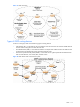
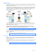
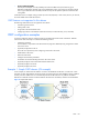
The following figure shows authentication configured for area 0 with the password test. Simple authentication is
also configured for the virtual link between area 2 and area 0. Area 1 is not configured for OSPF authentication.
Figure 20 OSPF authentication
To configure simple plain text OSPF passwords on the switches shown in the figure use the following commands:
1. Enable OSPF authentication for Area 0 on switches 1, 2, and 3.
>> # /cfg/l3/ospf/aindex 0/auth password