
ProLiant BL p-Class GbE2 Interconnect Switch Application Guide
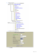
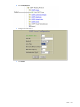

OSPF 128
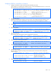
e. Configure the OSPF Interface 2, and attach it to the stub area 1.
f. Click Submit.
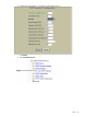
6. Apply, verify, and save the configuration.
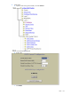
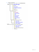
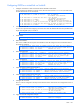
Example 2: Virtual links
In the example shown in the following figure, area 2 is not physically connected to the backbone as is usually
required. Instead, area 2 will be connected to the backbone via a virtual link through area 1. The virtual link
must be configured at each endpoint.
Figure 22 Configuring a virtual link