
ProLiant BL p-Class GbE2 Interconnect Switch Application Guide

High availability 152
Active-Active configuration
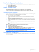
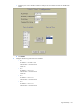
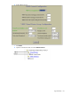
The following figure shows an example configuration, where two switches are used as VRRP routers in an active-
active configuration. In this configuration, both switches respond to packets.
Figure 27 Active-Active high availability configuration
Although this example shows only two switches, there is no limit on the number of switches used in a redundant
configuration. It is possible to implement an active-active configuration across all the VRRP-capable switches in a
LAN.
Each VRRP-capable switch in an active-active configuration is autonomous. Switches in a virtual router need not
be identically configured.
In the scenario illustrated in the figure, traffic destined for IP address 10.0.1.1 is forwarded through the Layer 2
switch at the top of the drawing, and ingresses Switch A on port 19. Return traffic uses default gateway 1
(192.168.1.1). If the link between Switch A and the Layer 2 switch fails, Switch B becomes the Master because
it has a higher priority. Traffic is forwarded to Switch B, which forwards it to Switch A through the crosslink (ports
17-18). Return traffic uses default gateway 2 (192.168.2.1), and is forwarded through the Layer 2 switch at the
bottom of the drawing.
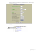
To implement the active-active example, perform the following switch configuration.
Task 1: Configure Switch A
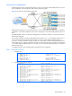
1. Configure ports.
/cfg/l2/vlan 10 (Select VLAN 10)
>> VLAN 10# ena (Enable VLAN 10)
>> VLAN 10# add 19 (Add port 19 to VLAN 10)
>> VLAN 10# ..
>> Layer 2# vlan 20 (Select VLAN 20)
>> VLAN 20# ena (Enable VLAN 20)
>> VLAN 20# add 20 (Add port 20 to VLAN 20)
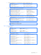
2. Configure client and server interfaces.
/cfg/l3/if 1 (Select interface 1)
>> IP Interface 1# addr 192.168.1.100 (Define IP address for interface 1)
>> IP Interface 1# vlan 10 (Assign VLAN 10 to interface 1)
>> IP Interface 1# ena (Enable interface 1)
>> IP Interface 1# ..
>> Layer 3# if 2 (Select interface 2)
>> IP Interface 2# addr 192.168.2.101 (Define IP address for interface 2)
>> IP Interface 1# vlan 20 (Assign VLAN 20 to interface 2)
>> IP Interface 2# ena (Enable interface 2)
>> IP Interface 2# ..
>> Layer 3# if 3 (Select interface 3)
>> IP Interface 3# addr 10.0.1.100 (Define IP address for interface 3)
>> IP Interface 3# mask 255.255.255.0 (Define subnet mask for interface 3)
>> IP Interface 3# ena (Enable interface 3)
>> IP Interface 2# ..
>> Layer 3# if 4 (Select interface 4)
>> IP Interface 4# addr 10.0.2.101 (Define IP address for interface 4)
>> IP Interface 4# mask 255.255.255.0 (Define subnet mask for interface 4)
>> IP Interface 4# ena (Enable interface 4)