
ProLiant BL p-Class GbE2 Interconnect Switch Application Guide


Basic IP routing 91
In this example, a corporate campus has migrated from a router-centric topology to a faster, more powerful,
switch-based topology. As is often the case, the legacy of network growth and redesign has left the system with a
mix of illogically distributed subnets.
This is a situation that switching alone cannot cure. Instead, the router is flooded with cross-subnet
communication. This compromises efficiency in two ways:
• Routers can be slower than switches. The cross-subnet side trip from the switch to the router and back again
adds two hops for the data, slowing throughput considerably.
• Traffic to the router increases, increasing congestion.
Even if every end-station could be moved to better logical subnets (a daunting task), competition for access to
common server pools on different subnets still burdens the routers.
This problem is solved by using GbE2 Interconnect Switches with built-in IP routing capabilities. Cross-subnet LAN
traffic can now be routed within the switches with wire speed Layer 2 switching performance. This not only eases
the load on the router but saves the network administrators from reconfiguring each and every end-station with
new IP addresses.
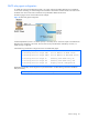
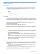
Take a closer look at the GbE2 Interconnect Switch in the following configuration example:
Figure 15 Switch-based routing topology
The GbE2 Interconnect Switch connects the Gigabit Ethernet and Fast Ethernet trunks from various switched
subnets throughout one building. Common servers are placed on another subnet attached to the switch. Primary
and backup routers are attached to the switch on yet another subnet.
Without Layer 3 IP routing on the switch, cross-subnet communication is relayed to the default gateway (in this
case, the router) for the next level of routing intelligence. The router fills in the necessary address information and
sends the data back to the switch, which then relays the packet to the proper destination subnet using Layer 2
switching.
With Layer 3 IP routing in place on the switch, routing between different IP subnets can be accomplished entirely
within the switch. This leaves the routers free to handle inbound and outbound traffic for this group of subnets.
To make implementation even easier, UDP Jumbo frame traffic is automatically fragmented to regular Ethernet
frame sizes when routing to non-Jumbo frame VLANS or subnets. This automatic frame conversion allows servers
to communicate using Jumbo frames, all transparently to the user.