
ProLiant BL p-Class GbE2 Interconnect Switch Application Guide


Basic IP routing 93
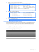
4. Configure the default gateways to the routers’ addresses.
Configuring the default gateways allows the switch to send outbound traffic to the routers:
>> IP Interface 5# ../gw 1 (Select primary default gateway)
>> Default gateway 1# addr 205.21.17.1(Assign IP address)
>> Default gateway 1# ena (Enable primary default gateway)
>> Default gateway 1# ../gw 2 (Select secondary default gateway)
>> Default gateway 2# addr 205.21.17.2 (Assign address)
>> Default gateway 2# ena (Enable secondary default gateway)
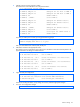
5. Enable, apply, and verify the configuration.
>> Default gateway 2# ../fwrd (Select the IP Forwarding Menu)
>> IP Forwarding# on (Turn IP forwarding on)
>> IP Forwarding# apply (Make your changes active)
>> IP Forwarding# /cfg/l3/cur (View current IP settings)
Examine the resulting information. If any settings are incorrect, make the appropriate changes.
6. Save your new configuration changes.
>> IP# save(Save for restore after reboot)
Using VLANs to segregate broadcast domains
In the previous example, devices that share a common IP network are all in the same broadcast domain. If you
want to limit the broadcasts on your network, you could use VLANs to create distinct broadcast domains. For
example, as shown in the following procedure, you could create one VLAN for the client trunks, one for the
routers, and one for the servers.
In this example, you are adding to the previous configuration.
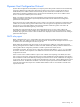
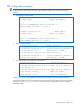
1. Determine which switch ports and IP interfaces belong to which VLANs.
The following table adds port and VLAN information:
Table 19 Subnet routing example: Optional VLAN ports
VLAN Devices IP Interface Switch Port VLAN #
1 First Floor Client Workstations 2 19 1
Second Floor Client Workstations 3 20 1
2 Primary Default Router 1 21 2
Secondary Default Router 1 22 2
3 Common Servers 1 4 1 3
Common Servers 2 4 2 3