HP ProLiant BL p-Class GbE2 Interconnect Switch User Guide Part number: 331399-004 Fourth edition: February 2006
Legal notices © 2004, 2006 Hewlett-Packard Development Company, L.P. The information contained herein is subject to change without notice. The only warranties for HP products and services are set forth in the express warranty statements accompanying such products and services. Nothing herein should be construed as constituting an additional warranty. HP shall not be liable for technical or editorial errors or omissions contained herein. Microsoft®, Windows®, and Windows NT® are U.S.
Contents Introduction Overview................................................................................................................................................ 5 Additional references ............................................................................................................................... 5 Features..................................................................................................................................................
Accessing the GbE2 Interconnect Switch ................................................................................................... 27 Logging on and configuring the GbE2 Interconnect Switch .......................................................................... 28 Supporting software and special considerations......................................................................................... 29 HP ProLiant BL p-Class C-GbE2 Interconnect Kit Regulatory Compliance Notices Class A equipment .
Introduction Overview This user guide provides installation and reference information for the following kits: • HP ProLiant BL p-Class C-GbE2 Interconnect Kit • HP ProLiant BL p-Class F-GbE2 Interconnect Kit Additional references Once the GbE2 Interconnect Switch is installed, you are ready to configure it. Detailed information about how to configure the GbE2 Interconnect Switch is available in the reference guides listed below. To obtain these guides, go to the HP website (http://www.hp.
Figure 2 HP ProLiant BL p-Class GbE2 Interconnect Switch and QuadSX Interconnect Module Features The ProLiant BL p-Class GbE2 Interconnect Switch and interconnect modules are designed for easy installation and high performance in an environment where traffic on the network and the number of users increases continually.
• Remote Monitoring (RMON) feature, which allows network devices to exchange network monitoring data. RMON performs the following major functions: • Gathers cumulative statistics for Ethernet interfaces • Tracks a history of statistics for Ethernet interfaces • Creates and triggers alarms for user-defined events • Quality of Service (QoS) feature, where the switch uses the Differentiated Services (RFCs 2474 and 2475) architecture to provide QoS functions.
GbE2 Interconnect Switch redundancy The ProLiant BL p-Class GbE2 Interconnect Switch offers several redundancy and failover features. With these features, the network configuration can be designed to allow for continued network access to each server blade in case of a component or link failure.
• Statistic monitoring including port utilization, data packets received/transmitted, port error packets, trunk utilization, and so on • Ping and trace route capability • Remote syslog with support for primary and secondary syslog server • Portable Diagnostic Station option to configure and diagnose a GbE2 Interconnect Switch and server blade removed from the rack • The ability to return the GbE2 Interconnect Switch to known good condition in case of firmware corruption • State information dump f
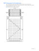
GbE2 Interconnect Switch architecture The ProLiant BL p-Class system provides integrated switching technology for network cable reduction. The following diagram illustrates the Ethernet signal connectivity between server bays and the interconnect bays through the backplane for the p-Class server enclosure.
The following diagram illustrates the Ethernet signal connectivity between server bays and the interconnect bays through the backplane for p-Class server enclosures with enhanced backplane components that support high-density blade servers. Figure 4 Ethernet signal connectivity for server enclosures with enhanced backplane components The interconnect switch does not affect or determine NIC enumeration and the associated mapping of NIC interfaces to interconnect switch ports.
HP Ethernet Connectivity Mapper utility (hpecm) The HP Ethernet Connectivity Mapper is a utility used to determine the NIC name enumeration and the associated mapping to switch ports. The physical connections between server blade network interface controllers (NICs) and switch ports depend on the server blade type and the enclosure backplane type, as described above. The logical NIC name enumeration depends on the operating system software (such as Local Area Connection, Local Area Connection 2, etc.
Layer 2 switching technology allows the GbE2 Interconnect Switch to look into data packets and redirect them based on the destination MAC address. This reduces traffic congestion on the network because packets, instead of being transmitted to all ports, are transmitted to the destination port only. IEEE 802.1Q-based Virtual Local Area Network The ProLiant BL p-Class GbE2 Interconnect Switch provides support for a total of 255 IEEE 802.
Interconnect Switch can also be uploaded to a TFTP server, a configuration file can be downloaded into a GbE2 Interconnect Switch from a TFTP server, and configuration settings can be saved to the TFTP server. Store and forward switching scheme The GbE2 Interconnect Switch provides a store and forward switching scheme that allows each packet to be buffered (stored) before it is forwarded to its destination. While this method creates latency, it improves reliability in a heavily used interconnect switch.
authenticated using a shared key that is not sent over the network. In addition, the remote administrator passwords are sent encrypted between the TACACS+ client (the switch) and the back-end TACACS+ server. The GbE2 Interconnect Switch supports: • Only standard ASCII inbound login authentication. PAP, CHAP, or ARAP login methods are not supported. Onetime password authentication is also not supported. • Authorization privilege levels of only 0, 3, and 6.
Redundant images in firmware The GbE2 Interconnect Switch can store up to two different software images, called image1 and image2, as well as boot software, called boot. When you download new software, you are given the ability to specify where it is to be placed: either into image1, image2, or boot. For example, if your active image is currently loaded into image1, you should probably load the new image software into image2.
Table 1 GbE2 Interconnect Switch front panel Item Description Status 6 Front panel RJ-45 Green = Link and no activity connector link activity LEDs Green flashing = Link and activity Amber = Port disabled Off = No link 7 Management status LED Flashing = Management session active Off = No management session active 8 Power status LED Green = Power on Amber = Stand-by mode Off = Power off 9 Link activity and speed LEDs Refer to the following figures and tables for LED assignments and functions.
Figure 7 GbE2 Interconnect Switch front panel NIC LED functions Table 3 GbE2 Interconnect Switch front panel NIC LED functions Item LED Description Status 1 Link speed Amber = 1000 Mb/s Green = 100 Mb/s Off = 10 Mb/s 2 Link activity Green = Link and no activity Green flashing = Link and activity Amber = Port disabled Off = No link QuadT2 Interconnect Module panel The QuadT2 Interconnect Modules are inserted into the bottom-left-most and bottom-right-most bays on the rear side of the server blade e
Table 4 QuadT2 Interconnect Module connectors Item Description 5 Port 22 RJ-45 connector for 10/100/1000 Mb uplink for Switch A 6 Port 21 RJ-45 connector for 10/100/1000 Mb uplink for Switch A 7 Port 20 RJ-45 connector for 10/100/1000 Mb uplink for Switch A 8 Port 19 RJ-45 connector for 10/100/1000 Mb uplink for Switch A Figure 9 QuadT2 Interconnect Module LEDs Table 5 QuadT2 Interconnect Module LEDs Item LED Description Status 1 Link activity Green = Link and no activity Green flashing = Li
Figure 10 QuadSX Interconnect Module connectors Table 6 QuadSX Interconnect Module connectors Item Description 1 Port 22 LC fiber connector for 1000SX uplink on Switch B 2 Port 21 LC fiber connector for 1000SX uplink on Switch B 3 Port 20 LC fiber connector for 1000SX uplink on Switch B 4 Port 19 LC fiber connector for 1000SX uplink on Switch B 5 Port 22 LC fiber connector for 1000SX uplink on Switch A 6 Port 21 LC fiber connector for 1000SX uplink on Switch A 7 Port 20 LC fiber connector fo
Setting up and installing the GbE2 interconnect switch Overview This chapter describes how to set up and install the ProLiant BL p-Class GbE2 Interconnect Switches and the interconnect modules. The setup and installation process includes the following tasks: 1. Installing the GbE2 Interconnect Switches and interconnect modules 2. Planning the GbE2 Interconnect Switch configuration 3. Cabling the GbE2 Interconnect Switch to the network 4. Powering up the GbE2 Interconnect Switch 5.
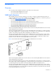
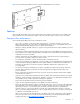
1. Insert the interconnect modules into the bottom-left and bottom-right module bays on the rear side of the server blade enclosure. IMPORTANT: Be sure that the interconnect modules are fully seated. The latch/handle will drop into place when the module is firmly seated. Figure 12 Installing the QuadT2 or QuadSX Interconnect Modules 2. Slide one GbE2 Interconnect Switch into the right interconnect bay in the front side of the server blade enclosure (1).
IMPORTANT: If you are replacing an existing GbE2 Interconnect Switch, or upgrading from a GbE Interconnect Switch, an RJ-45 Patch Panel, or an RJ-45 Patch Panel 2, and you have strict security requirements: Do not cable the GbE2 Interconnect Switch until after configuration. Or Connect the GbE2 Interconnect Switch to the optional Diagnostic Station.
5. On the rear side of the server blade enclosure, insert the new interconnect module into the bottom-left module bay. 6. On the front side of the server blade enclosure, slide a new GbE2 Interconnect Switch fully into the right interconnect bay. 7. Close the ejector lever and let the switch boot up completely, so that network connectivity is established. 8.
• User name and password settings • Default access to various management interfaces • Network Time Protocol (NTP) settings IMPORTANT: Refer to the “Runtime switching software default settings” appendix for a complete list of default configuration settings.
Table 8 User access levels User account Description and tasks performed Password Administrator The super user administrator has complete access to all menus, information, and configuration commands on the GbE2 Interconnect Switch, including the ability to change both the user and administrator passwords. admin Manually configuring a GbE2 Interconnect Switch A GbE2 Interconnect Switch can be configured manually using a command line interface, a browser-based interface, or an SNMP interface.
To connect the interconnect modules to the network: 1. Connect your network cables to the interconnect modules. For connector locations, refer to the “QuadT2 Interconnect Module panel” section or “QuadSX Interconnect Module panel” section in the “Introduction” chapter. 2. Gather your network cables for the right side of the rack. 3. Insert the end of the cable-retaining bracket (provided with the bus bar and power bus boxes) into the cable bracket (1). 4.
2. From a computer connected to the same network, use the IP address to access the GbE2 Interconnect Switch using a Web browser or Telnet application. This allows you to access the GbE2 Interconnect Switch browserbased interface (BBI) or command line interface (CLI). Once you have accessed the GbE2 Interconnect Switch, the GbE2 Interconnect Switch logon prompt is displayed.
Supporting software and special considerations The following supporting software is available to assist you in configuring and managing the GbE2 Interconnect Switch. • Server Blade and Power Management Module Firmware—Provides firmware and installation instructions required for proper rack location operation. • Utilities package and documentation—Provides utilities and documentation for GbE2 Interconnect Switch management. The utilities and documentation are located at http://www.hp.com/support.
HP ProLiant BL p-Class C-GbE2 Interconnect Kit Regulatory Compliance Notices Class A equipment This equipment has been tested and found to comply with the limits for a Class A digital device, pursuant to Part 15 of the FCC Rules. These limits are designed to provide reasonable protection against harmful interference when the equipment is operated in a commercial environment.
European Union Regulatory Notice This product complies with the following EU Directives: • Low Voltage Directive 73/23/EEC • EMC Directive 89/336/EEC CE Compliance of this product is valid only if powered with the correct HP-provided and CE marked AC adapter. If this product has telecommunication functionality, it also complies with the essential requirements of: • R&TTE Directive 1999/5/EC *For a notified body number refer to the product regulatory label.
BSMI Notice Japanese Notice Korean Notice HP ProLiant BL p-Class C-GbE2 Interconnect Kit Regulatory Compliance Notices 32
HP ProLiant BL p-Class F-GbE2 Interconnect Kit Regulatory Compliance Notices Class A equipment This equipment has been tested and found to comply with the limits for a Class A digital device, pursuant to Part 15 of the FCC Rules. These limits are designed to provide reasonable protection against harmful interference when the equipment is operated in a commercial environment.
European Union Regulatory Notice This product complies with the following EU Directives: • Low Voltage Directive 73/23/EEC • EMC Directive 89/336/EEC CE Compliance of this product is valid only if powered with the correct HP-provided and CE marked AC adapter. If this product has telecommunication functionality, it also complies with the essential requirements of: • R&TTE Directive 1999/5/EC *For a notified body number refer to the product regulatory label.
BSMI Notice Japanese Notice Korean Notice Laser compliance The fiber optic module contains a laser that is classified as a “Class 1 Laser Product” in accordance with US FDA regulations and the IEC 60825-1. The product does not emit hazardous laser radiation. WARNING! Use of controls or adjustments or performance of procedures other than those specified herein or in the laser product’s installation guide may result in hazardous radiation exposure.
Technical specifications Table 9 General specifications Standards IEEE 802.3 10Base-T Ethernet IEEE 802.3u 100Base-TX Fast Ethernet IEEE 802.3ab 1000Base-T Ethernet IEEE 802.3z 1000Base-SX Ethernet IEEE 802.1D Spanning Tree Protocol IEEE 802.1s Multiple Spanning Tree Protocol IEEE 802.1w Rapid Spanning Tree Protocol IEEE 802.1Q VLAN IEEE 802.3ac Frame Extensions for VLAN IEEE 802.3ad Link Aggregation Protocol (No LACP support) IEEE 802.3x Full-Duplex Flow Control ANSI/IEEE 802.
Table 9 General specifications Number of ports per GbE2 Interconnect Switch 16 x 10/100/1000-Mb/s Nway Ports dedicated to server blade for GbE2 Interconnect Switch communications 2 x 10/100/1000-Mb/s Nway Ports dedicated to communications between GbE2 Interconnect Switches A and B 4 10Base-T/100Base-TX/1000Base-T RJ-45 ports or 4 1-Gigabit LC ports (depending on C-GbE2 or F-GbE2 kit options) 2 x 10Base-T/100Base-TX/1000Base-T RJ-45 front panel management ports, or additional uplink ports 1 x serial RS-232
Table 11 Performance specifications Transmission method Store-and-forward Memory 128MB main, 32MB flash, and 2 MB shared packet buffer memory per GbE2 Interconnect Switch MAC address table size 2K per GbE2 Interconnect Switch Packet forwarding rate 1,488,095 packets per second with 64 byte packets per port (for 1000 Mb/s) Maximum external port packet forwarding rate 6 X 1Gig port = 6 X 1,488,095 = 8,928,570 pps per GbE2 Interconnect Switch Best downlink external port packet forwarding rate ratio
Runtime switching software default settings This section provides the default settings for the GbE2 Interconnect Switch: • Table 12 contains general default settings for both Switch A and Switch B • Table 13 contains port names, VLANs, STP, trunking default settings for Switch A and Switch B Switch A and Switch B: general default settings Switch A and Switch B are configured with the following general default settings: Table 12 Switch A and Switch B: general default settings Setting Value Notice None
Table 12 Switch A and Switch B: general default settings Setting Value Bridge Hello Time 2 seconds Bridge Forward Delay 15 seconds Bridge Priority 32768 MAC Address Aging Time 300 seconds Port Priority 128 Path Cost 4 Static VLAN Entry Default VLAN (VID = 1) Port VID 1 for all ports Port Trunking Trunk Group 1, Enabled with Port 17 and 18 Port Trunking Load Sharing Algorithm The algorithm selects the following as forwarding ports for forwarding traffic: 1 2 3 For forwarding IP Packets
Table 12 Switch A and Switch B: general default settings Setting Value Serial Port Data Bit 8 Serial Port Parity Bit None Serial Port Stop Bit 1 Serial Port Flow Control None Default VLAN Default VLAN (VID=1) with all ports assigned including CPU, STG=1 NTP State Disabled NTP Server 0.0.0.0 NTP Resync Interval 720 minutes GMT Timezone Offset -06:00 Daylight Savings Time State Disabled System Up Time 0 days 00 :00 :00 Current Time RTC or NTP (00 :00 :00) Date None Syslog Host 0.
Table 12 Switch A and Switch B: general default settings Setting Value RADIUS Server Timeout 3 RADIUS Backdoor for Telnet Access Disabled Re-ARP Period in Minutes 10 MSTP Disabled MSTP Default Mode RSTP MSTP Region Name None MSTP Region Version 1 MSTP Max Hop Count 20 CIST Bridge Max Age 20 seconds CIST Bridge Hello Time 2 seconds CIST Bridge Forward Delay 15 seconds CIST Bridge Priority 32768 CIST MAC Address Aging Time 300 seconds CIST Port Priority 128 CIST Port Path Cost 2
Table 12 Switch A and Switch B: general default settings Setting Value UFD Link to Disable – Ports None UFD Link To Disable -- Trunks None RMON History Group Number None RMON History Interface MIB to Monitor None RMON History Number of Requested Buckets 30 RMON History Polling Interval 1800 RMON History Owner None RMON Event Group Number None RMON Event Description None RMON Event Type None RMON Alarm Group Number None RMON Alarm MIB to Monitor None RMON Alarm Interval 1800 RMON
Table 12 Switch A and Switch B: general default settings Setting Value 802.1x – suptmout 30 802.1x – syrtmout 30 802.1x – maxreq 2 802.1x – raperiod 3600 802.
Switch A and Switch B: port names, VLANs, STP, trunking default settings IMPORTANT: If you have the ProLiant BL p-Class F-GbE2 Interconnect Kit option with the QuadSX Interconnect Modules, the management interface supports only 1000M/Full and Auto options for the Speed/Duplex fields for Gigabit uplink ports. The fiber QuadSX Interconnect Module supports only 1000-Mb/s (Gigabit) speed, and not 10-Mb/s or 100-Mb/s.
Table 13 Switch A and Switch B: port names, VLANs, STP, and trunking default settings Port type Port no.
Performing a serial download Introduction You can perform a serial download of the new GbE2 Interconnect Switch Operating System firmware, or Boot Code firmware if you want to upgrade a GbE2 Interconnect Switch directly from any existing operating system (OS) or Boot Code images.
5. After you see the message displayed in step 4, reconfigure your terminal emulation console with the following parameters. Parameter Value Baud Rate 115200 Data Bits 8 Parity None Stop Bits 1 Flow Control None 6. Press Enter several times on the keyboard of the PC that is connected to the console port of the GbE2 Interconnect Switch. When the console port is successfully communicating with the PC, indicating readiness for image transfer, you see continuous C’s: CCCCCCCCCCCCCCCCC 7.
Serial upgrade of operating system firmware procedure Use the following procedure to perform a serial upgrade of the GbE2 Interconnect Switch Operating System firmware image usually named pGbE2_100.bin. 1. Using the null modem cable, connect the console port of a GbE2 Interconnect Switch to the serial port of your PC that supports XModem/1K XModem. 2.
6. Press Enter several times on the keyboard of the PC that is connected to the console port of the GbE2 Interconnect Switch. When the console port is successfully communicating with the PC, indicating readiness for image transfer, you see continuous C’s: CCCCCCCCCCCCCCCCC 7. Make sure that the new Switch Operating System firmware file is available on the computer. This file can be downloaded from the CD that is shipped with the GbE2 Interconnect Switch or from http://www.hp.com/support. 8.
10. After extracting the image, the system prompts you to select which current operating system image (image1 or image2) needs to be updated by the new operating system image. It also provides an option (n) not to update any and to quit the update procedure. Depending on your selection, 1 or 2, the system updates image1 or image2 on the flash and a message with a progress indicator displays as shown below.
SNMP MIBs support Introduction Management and statistics information is stored in the GbE2 Interconnect Switch in the Management Information Base (MIB). The GbE2 Interconnect Switch supports several standard MIBs. Values for MIB objects can be retrieved with any SNMP-based network management software. In addition to the standard MIBs, the switch also supports its own proprietary enterprise MIB as an extended Management Information Base.
• cpqsinfo.mib—Switch identification information • cpqhost.mib—Switch identification information • bt2Network.mib • bt2Physical.mib • bt2Switch.mib • bt2acl.mib • bt2qos.mib • bt2trap.mib • cpqhost.mib • cpqrack.mib • cpqsinfo.mib • dot1x.mib • hpswitchpl.mib • ieee8023ad.mib • rfc1213.mib • rfc1493.mib • rfc1573.mib • rfc1643.mib • rfc1757.mib • rfc1850.mib • rfc1907.mib • rfc2037.mib • rfc2571.mib • rfc2572.mib • rfc2573.mib • rfc2574.mib • rfc2575.
The following are the enterprise SNMP traps supported in the GbE2 Interconnect Switch: Table 14 Supported enterprise SNMP traps Trap name Description bt2SwDefGwUp Signifies that the default gateway is alive. bt2SwDefGwDown Signifies that the default gateway is down. bt2SwDefGwInService Signifies that the default gateway is up and in service. bt2SwDefGwNotInService Signifies that the default gateway is alive but not in service.
Safe Mode configuration Introduction GbE2 Interconnect Switch configuration files are specified in text format. Trivial File Transfer Protocol (TFTP) or Secure Copy (SCP) services can to be used to upload and download these text-based configuration files. When these configuration files are downloaded and applied to the GbE2 Interconnect Switch, the GbE2 Interconnect Switch interprets the contents and applies it to the system as active configuration.
GbE2 Interconnect Switch replacement scenario using a Safe Mode configuration When an in-production GbE2 Interconnect Switch fails: 1. Remove the failed GbE2 Interconnect Switch. 2. Insert the spare GbE2 Interconnect Switch that was previously configured for safe operation. 3. Upgrade to new firmware if appropriate. 4. Download the correct configuration for that particular GbE2 Interconnect Switch.
Method 2: Via any switch management interface using TFTP functionality 1. Power up the switch using the Diagnostic Station or by inserting the switch in a non-production blade enclosure. After resetting the switch to factory settings (if required), login to the switch CLI via the serial console as Admin. 2. If the switch cannot get BootP assigned IP settings, configure the switch IP address settings so that it can access a TFTP server on the attached network. 3.
Electrostatic discharge Overview To prevent damage to the system, be aware of the precautions you need to follow when setting up the system or handling parts. A discharge of static electricity from a finger or other conductor may damage system boards or other static-sensitive devices. This type of damage may reduce the life expectancy of the device. To prevent electrostatic damage, observe the following precautions: • Avoid hand contact by transporting and storing products in static-safe containers.
RJ-45 pin specification When connecting the HP ProLiant BL p-class GbE2 Interconnect Switch to a switch, bridge, or hub, an Ethernet cable is necessary. The following figure displays the standard RJ-45 receptacle/connector for 10/100 Mb/s and Gigabit over Copper ports. Table 15 indicates the pin number and wire color assignments for the switch-to-network adapter card connection, and the Ethernet cable for the switch-to-switch, switch-to-hub, or switch-to-bridge connection.
Troubleshooting This section provides information on solutions to problems that may occur during the configuration and operation of a ProLiant BL p-Class GbE2 Interconnect Switch. The following tables provide steps to take before calling your service representative. Following are four tables with basic troubleshooting information: • Setting up and accessing—Table 17 contains general troubleshooting information about setting up and accessing the GbE2 Interconnect Switch.
Table 17 Troubleshooting: Setting up and accessing Problem Possible cause Possible solution The RJ-45 connector on the switch or LED • is faulty. • After checking and replacing the cable, if no link LED displays, check whether the port is transferring data. If yes, the LED is faulty. If no, it could be a faulty RJ-45 connector. Call your service representative. This could be caused by using a crossover cable instead of a straight-through cable.
Table 17 Troubleshooting: Setting up and accessing Problem Possible cause Possible solution Password is not accepted by the GbE2 Interconnect Switch using the remote console interface immediately after a reboot. The GbE2 Interconnect Switch is still working on network convergence. Wait up to 10 seconds, and the password should be accepted. Cannot connect to the GbE2 Interconnect Switch console interface remotely using SSH. The GbE2 Interconnect Switch IP address • may not be configured or correct.
Table 18 Troubleshooting: Configuring Problem Possible cause Possible solution After connecting more than one port to another switch or destination device, the port activity LEDs continuously indicate activity. Because there are multiple links across this device and the destination device, they form loops, which cause broadcast storms. Enable STP if you want multiple links. This setting prevents loops and maintains standby links for resilience in case of primary link failure.
Table 19 Troubleshooting: Using a TFTP server Problem Possible cause While using TFTP to download firmware, The TFTP server is not available to the GbE2 Interconnect Switch fails to connect to or there is connectivity failure connect to the TFTP server, or after between the switch and TFTP server. connection the download fails. The firmware file is not found on the TFTP server. The file name could be wrong.
Table 20 Troubleshooting: Upgrading firmware using the serial port Problem Possible cause Possible solution After forcing the GbE2 Interconnect Switch into the download mode, the console screen displays a message to change the baud rate for your terminal emulation session for XModem transfer and does not display CCCC…. Your terminal emulation session baud rate does not match the GbE2 Interconnect Switch serial console baud rate in the download mode.
Index A H N accessing switch: procedure, 27; RADIUS authentication, 14 administrator account password, 26 architecture, switch, 10 hardware installation, 21 HP ProLiant BL p-Class C-GbE2 Interconnect Kit: features, 5 HP ProLiant BL p-Class F-GbE2 Interconnect: Kit features, 5 HP ProLiant BL p-Class GbE2 Interconnect Switch: architecture, 10; external components, 16; installing, 21; SNMP MIBs support, 52; supported technologies, 12; troubleshooting, 60 HP ProLiant BL p-Class GbE2 Storage Connectivity Kit
standards, IEEE/ANSI, 36 store and forward switching scheme, 14 switch replacement, safe mode, 56 configurations, 26; overview, 13; XML configuration, 55 troubleshooting, 60 trunking feature, overview, 13 T U templates, safe mode: location, 56; modification, 56 Trivial File Transfer Protocol (TFTP) server: multiple switch upgrading from a GbE Interconnect Switch, 23 upgrading from RJ-45 patch panels, 24 user account password, 25 users, XML configuration, 55 V virtual local area networks (VLANs): feat