HP ProLiant BL p-Class System Diagnostic Station User Guide Part Number 230859-004 April 2004 (Fourth Edition)
© Copyright 2002, 2004 Hewlett-Packard Development Company, L.P. Microsoft and Windows are U.S. registered trademarks of Microsoft Corporation. Intel and Pentium are trademarks or registered trademarks of Intel Corporation or its subsidiaries in the United States and other countries. Java is a US registered trademark of Sun Microsystems, Inc. Hewlett-Packard Company shall not be liable for technical or editorial errors or omissions contained herein.
Contents Abstract.......................................................................................................... 5 Diagnostic Station Kit Contents................................................................... 6 Warnings and Cautions ................................................................................ 7 Using the Diagnostic Cable or the Local I/O Cable for Configuration or Diagnostic Procedures .................................................................................
BSMI Notice .....................................................................................................................
Abstract This document provides instructions for cabling the diagnostic station to an HP ProLiant BL p-Class server blade to enable out-of-rack communication with the server blade.
Diagnostic Station Kit Contents NOTE: You may need additional items, depending on the server blade you are using.
Table 1: Diagnostic Station Kit Contents continued Item Description 4 DC power cord (for server blade)1 5 DC power cord (for interconnect switch) 6 AC power cord 2 7 Network cable with RJ-45 connectors Not shown Documentation CD-ROM Not shown This installation guide 1 For information about connecting the diagnostic station to an interconnect switch using this DC power cord, refer to the documentation that ships with the interconnect switch.
CAUTION: Properly ground yourself before beginning any installation procedure. Electrostatic discharge can damage electronic components. For more information about electrostatic discharge, refer to the setup and installation guide. CAUTION: Disconnect the local I/O cable when not in use. The port and connector do not provide a permanent connection. Rear iLO connector performance degrades when the local I/O cable is in use, even when the iLO connector on the cable is not in use.
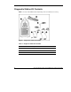
Identifying Diagnostic and Local I/O Cable Connectors Use Figure 3 and Table 2 to identify diagnostic cable and local I/O cable connectors. Figure 3: Diagnostic cable (top) and local I/O cable (bottom) connectors Table 2: Diagnostic and Local I/O Cable Connectors Item Connector Name Connector Description Diagnostic cable (top) 1 Server blade connector Provides a direct connection to the server blade.
Table 2: Diagnostic and Local I/O Cable Connectors continued Item 3 Connector Name Connector Description Kernel debug connector 2 Requires a null modem serial cable and enables trained personnel to perform advanced diagnostic procedures. Local I/O cable (bottom) 3 4 Video connector Provides video capability. 5 USB connector 1 Provides USB connection enabling direct connection to the server blade. 6 USB connector 2 Provides USB connection enabling direct connection to the server blade.
Installing the Diagnostic Cable or the Local I/O Cable To install the diagnostic cable or the local I/O cable with the diagnostic station, see the “Diagnostic Station” section. To install the diagnostic cable on a server blade in the rack, refer to the setup and installation guide included with the server blade. Diagnostic Station The diagnostic station enables you to power up and communicate with a server blade or an interconnect switch outside of the rack environment.
For more information about installing hardware options and performing troubleshooting procedures, refer to the p-Class server blade setup and installation guides on the Documentation CD and to the documentation that ships with the interconnect switch. Diagnostic Station Components Use Figure 4 and Table 3 to identify diagnostic station components.
Table 3: Diagnostic Station Components continued Item Component Description 5 Reserved for additional AC power 6 AC power input connector 7 DC power output connectors 8 Data transfer port 9 NIC LEDs 10 Power On/Off button 11 Power and health LED * This component does not apply to the ProLiant BL30p server blade. Accessing the Cable Storage Area To access the cable storage area: 1. Turn the locking latch clockwise (1). 2. Pull down the cable storage area access door (2).
Client PC Requirements Observe the following minimum software and hardware requirements for a client PC: • Intel® Pentium® III or higher processor (700 MHz or greater recommended) • 128 MB of RAM • Microsoft® Windows® 2000 Professional or Microsoft Windows XP operating system • Microsoft Internet Explorer 5.
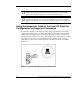
Preparing the Server Blade for Connection Before connecting the diagnostic station to a server blade: 1. Power down the server blade. 2. Remove the server blade from the server blade enclosure in the rack. IMPORTANT: If the server blade is a ProLiant BL30p, install the server blade into a blade sleeve and connect the blade sleeve to a diagnostic station. 3. Place the server blade on a flat, level workspace. 4. Perform any upgrade or maintenance actions and replace the access panel.
— With USB devices—Connect the local I/O cable to the I/O port on the front of the server blade. This connection enables you to connect a monitor through the video connector and various USB devices, such as a USB keyboard, USB mouse, USB floppy, and/or a USB CD-ROM, directly to the server. NOTE: Use of the USB hub is optional as the hub is only required when connecting three or more USB devices.
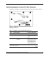
To connect a client PC to the server using the direct cabling method: 1. Thread the DC power cord for a server blade or blade sleeve through the opening in the VHDM converter (1). 2. Snap the cord into place in the VHDM converter (2).
3. Place the VHDM converter on the rear of the server blade or the blade sleeve by inserting the tab into the right side (1), making sure the pins on the left side are properly aligned. 4. Tighten the thumbscrew to secure the VHDM converter to the server blade (2) or the blade sleeve. 5. Insert the DC power cord into one of the diagnostic station DC power connectors (3).
6. Connect the data transfer cable to the VHDM converter on the server blade (1) or the blade sleeve. 7. Connect the other end of the data transfer cable to the diagnostic station (2).
8. Connect the server blade to the client PC using the diagnostic cable. If you are using the local I/O cable to connect to the I/O port, go to step 9. CAUTION: Disconnect the diagnostic cable when not in use. The port and connector do not provide a permanent connection. Rear iLO connector performance degrades when the local I/O cable is in use, even when the iLO connector on the cable is not in use. a. Connect the network cable with RJ-45 connectors to the client PC (1). b.
9. Connect the server blade to a client PC using the local I/O cable. CAUTION: Disconnect the local I/O cable when not in use. The port and connector do not provide a permanent connection. Rear iLO connector performance degrades when the local I/O cable is in use, even when the iLO connector on the cable is not in use. a. Connect the network cable with RJ-45 connectors to the client PC (1). b. Connect the other end of the RJ-45 network cable to the local I/O cable (2).
IMPORTANT: If you are connecting to a ProLiant BL30p server blade, the server blade must be installed in the left slot of the blade sleeve on a flat surface.
IMPORTANT: The diagnostic station ships with several AC power cords of different outlet plug configurations. Be sure to select the proper AC power cord for the electrical service. 10. Connect the AC power cord to the diagnostic station (1). 11. Connect the other end of the AC power cord to an AC outlet (2). NOTE: Previously installed components have been removed for clarity.
Refer to Figure 13 for the completed direct cabling method using diagnostic cable (left) and the local I/O cable (right). Figure 13: Completed direct cabling method (front and rear views) using the diagnostic cable (1) and the local I/O cable (2) to connect to iLO After the direct cabling method is complete, the server blade and diagnostic station are ready for use. See the “Powering Up the Server Blade” section.
CAUTION: Disconnect the local I/O cable when not in use. The port and connector do not provide a permanent connection. Rear iLO connector performance degrades when the local I/O cable is in use, even when the iLO connector on the cable is not in use. 3. Connect the monitor to the video connector on the local I/O cable. 4. Connect a USB hub to the USB connector on the local I/O cable. NOTE: Use of the USB hub is optional as you may connect to the server using any combination of USB devices.
Refer to Figure 14 for the completed direct cabling method using USB devices and the local I/O cable. Figure 14: Completed direct cabling method (front and rear view) using the local I/O cable and USB devices to directly access the server blade After the direct cabling method is complete, the server blade and diagnostic station are ready for use. See the “Powering Up the Server Blade” section.
IMPORTANT: The DHCP server assigns the IP address to the iLO NIC. The DHCP server is not necessary if you have configured iLO and/or any other connected NICs to use a static IP address. To connect with the network cabling method: 1. Follow steps 1 through 7 of “Using the Direct Cabling Method with a Client PC” to make the connections from the server blade to the diagnostic station.
IMPORTANT: If you are using the diagnostic station for operating system deployment or file management, connect an additional network cable with RJ-45 connectors between the NIC 1 connector and the hub. 4. Connect an additional network cable with RJ-45 connectors between the client PC (1) and the hub (2). Figure 16: Connecting a network cable to the client PC and the hub 5. Connect the following items to the hub: a. Network cable with RJ-45 connectors from the diagnostic station NIC 4 connector b.
Figure 17 shows a completed network cabling method with the DHCP server (1) and the hub (2). IMPORTANT: For operating system deployment or file management, an optional server can be connected to the hub. NOTE: Connecting the diagnostic cable to the diagnostic port or connecting the local I/O cable to the I/O port automatically disables the iLO connection on the rear of the diagnostic station.
3. Power up the client PC in accordance with its own documentation. NOTE: iLO may take up to 90 seconds to establish a secure network connection. IMPORTANT: If tasks are to be performed on more than one ProLiant BL30p server blade, power down the first server blade and remove it from the blade sleeve. Then, install the next server blade in the left bay of the blade sleeve when the blade sleeve is laying on a flat surface.
Network Cabling Method In this method, the client PC is connected to the iLO using a hub/switch and the network connections of the diagnostic station. The iLO default configuration enables the server blade to obtain its IP address from a DHCP server. NOTE: If you have edited the configuration to use a static IP address, iLO uses this same static IP address when you connect with the network cabling method.
GbE Interconnect Switch You can configure or troubleshoot a GbE interconnect switch in an out-of-rack environment. In this situation, the diagnostic station provides power to the interconnect switch. Use the following items from the diagnostic station kit: • Diagnostic station • DC power cord (for interconnect switch) • Network cable with RJ-45 connectors • AC power cord For setup and operating instructions, refer to the documentation that ships with the interconnect switch.
Modifications The FCC requires the user to be notified that any changes or modifications made to this device that are not expressly approved by Hewlett-Packard Company may void the user's authority to operate the equipment. Cables Connections to this device must be made with shielded cables with metallic RFI/EMI connector hoods in order to maintain compliance with FCC Rules and Regulations.
• EN61000-3-3 (IEC61000-3-3) – Power Line Flicker • EN 60950 (IEC 60950) – Product Safety Japanese Notice Korean Notice BSMI Notice 34 HP ProLiant BL p-Class System Diagnostic Station User Guide