HP ProLiant BL p-Class System Setup and Installation Guide January 2003 (Second Edition) Part Number 230852-002 HP CONFIDENTIAL Writer: Christine Portillo File Name: a-frnt.
Hewlett-Packard Company shall not be liable for technical or editorial errors or omissions contained herein. The information in this document is provided “as is” without warranty of any kind and is subject to change without notice. The warranties for HP products are set forth in the express limited warranty statements accompanying such products. Nothing herein should be construed as constituting an additional warranty.
Contents About This Guide Audience Assumptions..................................................................................................... vii Important Safety Information ........................................................................................... vii Symbols on Equipment .................................................................................................... vii Rack Stability .............................................................................................
Contents Temperature Requirements .......................................................................................2-3 Power Requirements..................................................................................................2-4 Grounding Requirements ..........................................................................................2-4 Rack Warnings.................................................................................................................
Contents Appendix A Regulatory Compliance Notices Regulatory Compliance Identification Numbers............................................................ A-1 Federal Communications Commission Notice ............................................................... A-1 Class A Equipment .................................................................................................. A-2 Modifications ...........................................................................................................
Contents Appendix E Specifications Server Blade Enclosure................................................................................................... E-1 Power Enclosures............................................................................................................ E-3 North America/Japan................................................................................................ E-3 International .......................................................................................
About This Guide This guide provides step-by-step instructions for installation and reference information for operation, troubleshooting, and future upgrades of the HP ProLiant BL p-Class System. Audience Assumptions This guide is for the person who installs, administers, and troubleshoots servers. HP assumes you are qualified in the servicing of computer equipment and trained in recognizing hazards in products with hazardous energy levels.
About This Guide This symbol indicates the presence of hazardous energy circuits or electric shock hazards. Refer all servicing to qualified personnel. WARNING: To reduce the risk of injury from electric shock hazards, do not open this enclosure. Refer all maintenance, upgrades, and servicing to qualified personnel. This symbol indicates the presence of electric shock hazards. The area contains no user or field serviceable parts. Do not open for any reason.
About This Guide Rack Stability WARNING: To reduce the risk of personal injury or damage to the equipment, be sure that: • The leveling jacks are extended to the floor. • The full weight of the rack rests on the leveling jacks. • The stabilizing feet are attached to the rack if it is a single-rack installation. • The racks are coupled together in multiple-rack installations. Symbols in Text These symbols may be found in the text of this guide.
About This Guide Related Documents For additional information on the topics covered in this guide, refer to the following documentation: • HP ProLiant BL p-Class System Maintenance and Service Guide • HP ProLiant BL p-Class Server Blade Setup and Installation Guide • HP ProLiant BL p-Class System Hardware Installation and Configuration Poster • Servers Troubleshooting Guide • Integrated Lights-Out User Guide • ROM-Based Setup Utility User Guide • White paper: ProLiant BL p-Class System Overvie
About This Guide • Product serial number • Product model name and number • Applicable error messages • Add-on boards or hardware • Third-party hardware or software • Operating system type and revision level HP Website The HP website has information on this product as well as the latest drivers and flash ROM images. You can access the HP website at www.hp.com. Authorized Reseller For the name of the nearest authorized reseller: • In the United States, call 1-800-345-1518.
About This Guide For ordering information, refer to www.hp.com Reader’s Comments HP welcomes your comments on this guide. Please send your comments and suggestions by e-mail to ServerDocumentation@hp.com. xii HP ProLiant BL p-Class System Setup and Installation Guide HP CONFIDENTIAL Writer: Christine Portillo File Name: a-frnt.
1 System Features The HP ProLiant BL p-Class system offers a range of power and performance for large-volume rollouts in space-constrained environments. The ProLiant BL p-Class system architecture is a revolutionary step in server modularity that stresses rapid deployment and remote management. Minimum Hardware Requirements To set up the system, you must choose and install several of the modular components. The following hardware components are required to operate a ProLiant BL p-Class system.
System Features Figures 1-1 and 1-2 and Tables 1-1 and 1-2 identify system components. The scalable configuration is shown on the left, and the full-rack 42U configuration (two pairs of mini bus bars) is shown on the right. Figure 1-1: System components in a 42U rack (front) 1-2 HP ProLiant BL p-Class System Setup and Installation Guide HP CONFIDENTIAL Writer: Christine Portillo File Name: b-ch1 System Features.
System Features Table 1-1: System Components (Front) Item Description 1 Server blade enclosures 2 Server blades 3 Interconnects 4 Power enclosures 5 Hot-plug power supplies HP ProLiant BL p-Class System Setup and Installation Guide HP CONFIDENTIAL Writer: Christine Portillo File Name: b-ch1 System Features.
System Features Figure 1-2: System components in a 42U rack (rear, cables removed for clarity) Table 1-2: System Components (Rear) Item Description 1 Server blade enclosures 2 Interconnect modules continued 1-4 HP ProLiant BL p-Class System Setup and Installation Guide HP CONFIDENTIAL Writer: Christine Portillo File Name: b-ch1 System Features.
System Features Table 1-2: System Components (Rear) continued Item Description 3 Power enclosures 4 Mini bus bars* (pair) 5 Scalable bus bars (pair) * Two mini bus bar pairs support a full-rack (42U) configuration. Power Components The system requires bus bars or power bus boxes to distribute power to the server blade enclosures. Table 1-3 identifies enclosure capabilities for each device.
System Features Configuration and Management Features HP offers an extensive set of features and optional tools to support effective server blade configuration and management: • ProLiant Essentials Rapid Deployment Pack • ROM-Based Setup Utility (RBSU) • Option ROM Configuration for Arrays (ORCA) Utility • Redundant ROM Support • Remote ROM flash • ROMPaq Utility • Insight Manager 7 • Diagnostics Utility • Automatic Server Recovery-2 (ASR-2) • Integrated Management Log (IML) For more de
System Features Diagnostic Features Hardware, software, and firmware diagnostic tools available for your use include: • System LEDs • Diagnostic station • Diagnostic cable • Diagnostic port • Insight Manager 7 • Power-On Self Test (POST) • Server Diagnostics For more information about diagnostic tools, refer to the software documentation that ships with the system.
2 Planning the Installation For maximum performance and availability from the server blade, be sure that the operating environment meets the required specifications for the following: • Rack compatibility • Space and airflow • Temperature • Power • Electrical grounding • Floor strength Refer to the “Optimum Environment” section in this chapter and the ProLiant BL p-Class System Overview and Planning white paper that is available on the Documentation CD or at www.hp.
Planning the Installation Optimum Environment When installing the ProLiant BL p-Class system in a rack, select a location that meets the environmental standards described in the following paragraphs. Rack Requirements The ProLiant BL p-Class system is compatible with the following racks: • 42U, 36U, and 22U Compaq branded racks — Compaq branded 10000 and 9000 Series racks (42U, 36U, and 22U) are compatible. (The system is optimized for 10000 Series racks.
Planning the Installation ProLiant servers draw in cool air through the front door and expel warm air through the rear door. Therefore, the front and rear rack doors must be adequately ventilated to enable ambient room air to enter the cabinet, and the rear door must be adequately ventilated to enable the warm air to escape from the cabinet. IMPORTANT: Do not block the ventilation openings.
Planning the Installation Power Requirements WARNING: Risk of fire or damage to the equipment. Each AC power cord for the power enclosure has an electrical rating based on the model and power supply configuration. The rating is marked on the side of the enclosure. It is important that the system be configured and loaded according to the guidelines in the ProLiant BL p-Class System Overview and Planning white paper.
Planning the Installation Rack Warnings Before installing the rack, observe the following warnings: WARNING: To reduce the risk of personal injury or equipment damage, always be sure that the rack is adequately stabilized before installing or removing a component. WARNING: To reduce the risk of personal injury or equipment damage, be sure that: • The leveling jacks are extended to the floor. • The full weight of the rack rests on the leveling jacks.
Planning the Installation System Warnings and Cautions Before installing the system, carefully review the following warnings and cautions: WARNING: To reduce the risk of personal injury or damage to equipment, heed all warnings and cautions throughout the installation instructions. WARNING: To reduce the risk of electric shock or damage to the equipment, only enter or perform service on specific parts of the system as instructed in the user documentation.
Planning the Installation WARNING: The power enclosure and the server blade enclosure are very heavy. To reduce the risk of personal injury or damage to the equipment: • Observe local occupational health and safety requirements and guidelines for manual material handling. • Remove hot-plug power supplies and server blades from their enclosures before installing or removing the enclosures.
3 Installing System Hardware This chapter provides installation procedures for the following system infrastructure components: • Power enclosures • Server blade enclosures • Hot-plug power supplies • Interconnects and their respective modules • Bus bars You can also refer to the installation procedures on the HP ProLiant BL p-Class System Hardware Installation and Configuration poster.
Installing System Hardware Measuring with the Rack Template Telco Rack Configurations If you are installing components in a telco rack, refer to the telco rack template and documentation that ship with the telco enclosure option kits. Power Bus Box Configurations If you are installing a power bus box configuration, refer to the power bus box rack template and documentation that ship with the power bus box option kit.
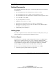
Installing System Hardware To install the rack rails and cage nuts: 1. Position yourself at the front of the rack. 2. Measure the depth of the rack. 3. Be sure that the rail locking gear is in the unlocked position (1). 4. Press the rail locking tab to unlock the rack rail (2). 5. Adjust the rack rail to the depth of the rack using the numbers on the rack rail as a guide (3). The depth of a Compaq branded rack (29 inches) is clearly indicated on the rack rails.
Installing System Hardware Figure 3-2: Inserting the rear of the rack rail 7. Compress the spring-loaded rack rail toward the rear of the rack (1). 8. Using the marks you made when measuring with the template, align the front of the right rail with the holes and release the rail, allowing it to lock into position (2). 9. Engage the locking gear (3).
Installing System Hardware CAUTION: Rack rails must be installed as tightly as possible. Failure to obtain a proper fit may result in damage to equipment. 10. Repeat steps 1 through 9 for the left rack rail. IMPORTANT: To ease installation, install all cage nuts for enclosures, bus bar hinges, and cable brackets at this time. 11. Using the marks you made when measuring with the template, install the cage nuts for enclosures, bus bar hinges, and the cable bracket.
Installing System Hardware Installing Enclosures into the Rack WARNING: Be sure that the power enclosure AC power cords are not connected to a power source. WARNING: To reduce the risk of personal injury and damage to the equipment, always begin by mounting the heaviest item on the bottom of the rack. Continue to populate the rack from the bottom to the top. Failure to do so may make the rack unstable. WARNING: Remove all hot-plug power supplies before loading a power enclosure into the rack.
Installing System Hardware 3. Align the enclosure guiding fins with the guiding groove in the rack rails. 4. Slide the enclosure fully into the rack (1). IMPORTANT: Be sure power cords and cables are accessible at the back of the rack. 5. Tighten the thumbscrews to secure the enclosure in the rack (2). IMPORTANT: Be sure that the guiding fins on the enclosure seat properly in the guiding groove on the rack rail.
Installing System Hardware Figure 3-6: Loading a server blade enclosure, with blanks, into the rack 6. Repeat steps 1 through 5 for subsequent enclosures. After installing enclosures, you can install hot-plug power supplies and interconnects. Refer to the “Hot-Plug Power Supplies” and “Interconnects” sections in this chapter. You can also perform some cabling procedures. Refer to Chapter 4, “Cabling and Powering Up the System.
Installing System Hardware Identifying Power Supply Bays Use Figure 3-7 and Table 3-1 to identify power supply bays.
Installing System Hardware Installation Guidelines Observe the following requirements when installing a hot-plug power supply into the power enclosure: • Always install hot-plug power supplies in the bottom power enclosure first, if more than one power supply enclosure is installed. • HP recommends installing hot-plug power supplies in a redundant configuration, as described in Table 3-2.
Installing System Hardware Installing a Hot-Plug Power Supply To install a hot-plug power supply: CAUTION: Always install either a hot-plug power supply or a power supply blank to maintain proper airflow and cooling in the power enclosure. Improper airflow can lead to thermal damage. 1. Press the release button (1). 2. Open the release lever (2). 3. Slide the hot-plug power supply fully into the bay (3). 4. Close the release lever (4). Figure 3-8: Installing a hot-plug power supply 5.
Installing System Hardware Installing a Power Supply Blank To install a power supply blank: CAUTION: Always install either a hot-plug power supply or a power supply blank to maintain proper airflow and cooling in the power enclosure. Improper airflow can lead to thermal damage. 1. Slide the power supply blank into the power supply bay until the blank is fully seated. Figure 3-9: Installing a power supply blank 2. Repeat step 1 to fill all empty power supply bays.
Installing System Hardware Interconnects Each server blade enclosure requires a pair of interconnects to provide network access for data transfer or remote management. The leftmost and rightmost bays of each server blade enclosure are interconnect bays for these devices. IMPORTANT: Interconnect options vary. A server blade enclosure requires a pair of interconnects of the same type. Do not mix two types of interconnects in the same enclosure. (Figures 3-10 through 3-12 show the RJ-45 patch panel.
Installing System Hardware To install the interconnect (front of rack): 1. Press the release button (1). 2. Open the ejector lever (2). Figure 3-11: Unlocking an interconnect (RJ-45 patch panel shown) 3-14 HP ProLiant BL p-Class System Setup and Installation Guide HP CONFIDENTIAL Writer: Christine Portillo File Name: d-ch3 Installing System Hardware.
Installing System Hardware 3. Slide the interconnect into the server blade enclosure interconnect bay (1). 4. Close the ejector levers (2). 5. Repeat steps 1 through 4 for the second interconnect. Figure 3-12: Installing an interconnect (RJ-45 patch panel shown) If you installed interconnect switches, you must configure them with the appropriate software utilities. For more information, refer to the documentation that ships with the interconnect switch.
Installing System Hardware Power Distribution Components The system requires components to distribute -48 VDC power from the power enclosure or facility -48 VDC source to the server blade enclosures. Installation Guidelines Observe the following guidelines: • Always be sure to set the rack rail depth for enclosures between 73.66 cm and 76.20 cm (29 inches and 30 inches) for proper bus bar clearance in a rack with a rear rack door.
Installing System Hardware Figure 3-13: Installing cage nuts NOTE: Enclosures and cables have been removed from the following figures for clarity. 2. Align a bus bar hinge with the rack (1). 3. Slide the hinge toward the outside edge of the rack (2). 4. Install the screws to secure the hinge (3). Figure 3-14: Installing hinges HP ProLiant BL p-Class System Setup and Installation Guide HP CONFIDENTIAL Writer: Christine Portillo File Name: d-ch3 Installing System Hardware.
Installing System Hardware 5. Repeat steps 1 through 3 for the other three hinges. 6. Hang the bus bars on the hinges. Figure 3-15: Hanging the bus bars on the hinges 7. Insert the hinge nut into the bottom of the top hinge (1). 8. Insert the hinge bolt and use a 4 mm (5/32 inch) Allen wrench to tighten the bolt into the nut (2).
Installing System Hardware 9. Repeat steps 7 and 8 for each hinge. The bus bars ship with locking latches for securing the bus bars and a cable bracket for routing network cables. These components are installed after cabling is complete. For cabling procedures, refer to Chapter 4, “Cabling and Powering Up the System.
4 Cabling and Powering Up the System Identifying System Components Figures 4-1 through 4-3 and Tables 4-1 through 4-3 identify connector and cable locations on system components: • Power enclosure and power management module • Server blade enclosure and server blade management module • Interconnects • Bus bars and power bus boxes The diagnostic station has multiple cabling configurations for configuration and diagnostic purposes.
Cabling and Powering Up the System Enclosures and Management Modules Figure 4-1: Enclosures and management module components (rear) Table 4-1: Enclosure and Management Module Components Item Description 1 Server blade enclosure 2 Server blade management module 3 Server blade management module service port* 4 Server blade management link connectors (top to enclosure above, bottom to enclosure below) * The service port is for advanced diagnostics performed by qualified service personnel only.
Cabling and Powering Up the System Table 4-1: Enclosure and Management Module Components continued Item Description 5 DC power input connector for bus A 6 DC output power cable pairs (-48V and return) for bus A 7 Grounding cable screw 8 Power management link connector to enclosure above 9 Power enclosure AC circuit breakers (to hot-plug power supplies) for bus B (left) and bus A (right) 10 Power management module service port* 11 Power management link connector to enclosure below 12 Power
Cabling and Powering Up the System Scalable and Mini Bus Bar Components Figure 4-2: Scalable (shown on left) and mini (shown on right) bus bar components 4-4 HP ProLiant BL p-Class System Setup and Installation Guide HP CONFIDENTIAL Writer: Christine Portillo File Name: e-ch4 Cabling and Powering Up the System.
Cabling and Powering Up the System Table 4-2: Mini and Scalable Bus Bar Components Item Description 1 DC power output cables with couplers 2 DC circuit breakers 3 DC power input connector access 4 DC power input connector access cover HP ProLiant BL p-Class System Setup and Installation Guide HP CONFIDENTIAL Writer: Christine Portillo File Name: e-ch4 Cabling and Powering Up the System.
Cabling and Powering Up the System Power Bus Box Components Figure 4-3: Power bus box components (some internal pieces removed for clarity) Table 4-3: Power Bus Box Components Item 1 DC power input connectors 2 Access cover 3 DC power output cables with coupler (installed) Not shown 4-6 Description Circuit breaker (on opposite side) HP ProLiant BL p-Class System Setup and Installation Guide HP CONFIDENTIAL Writer: Christine Portillo File Name: e-ch4 Cabling and Powering Up the System.
Cabling and Powering Up the System Cabling the System Overview After all system hardware is installed, you can cable the components. Examples of system cabling for different configurations are available in the “Cabling Configuration Diagrams” section in this chapter. WARNING: To reduce the risk of electric shock or injury due to high current electrical energy, be sure that all power is completely disconnected at the source before beginning any power connections to the power bus bars or power bus box.
Cabling and Powering Up the System 3. Connect the grounding cable to the server blade enclosures, if you are using a facility DC power source. Refer to the “Grounding Cable in Facility DC Power Environments” section in this chapter. IMPORTANT: If the configuration does not include power enclosures, omit step 4. 4. Connect the load-balancing signal cable between power enclosures (scalable bus bar configuration only). Refer to the “Load-Balancing Signal Cable” section in this chapter. 5.
Cabling and Powering Up the System Figure 4-4: Scalable bus bar cabling configuration HP ProLiant BL p-Class System Setup and Installation Guide HP CONFIDENTIAL Writer: Christine Portillo File Name: e-ch4 Cabling and Powering Up the System.
Cabling and Powering Up the System Table 4-4: Scalable Bus Bar Configuration Item Description 1 Network cables (number of cables depends on interconnect option or solution) 2 Bus bar DC output power cables with couplers 3 Management module cables 4 Power enclosure DC output power cables 5 Power enclosure load-balancing signal cable 6 Power enclosure AC input power cords Mini Bus Bar Figure 4-5 identifies mini bus bar cabling for one power enclosure and three server blade enclosures.
Cabling and Powering Up the System Figure 4-5: Mini bus bar cabling configuration Table 4-5: Mini Bus Bar Configuration Item Description 1 Network cables (number of cables depends on interconnect option or solution) 2 Bus bar DC output power cables with couplers 3 Management module cables* 4 Power enclosure DC output power cables 5 Power enclosure AC input power cords * In a full-rack 42U solution, an additional management module cable connects modules between the two pairs of mini bus bars.
Cabling and Powering Up the System Power Bus Box Figure 4-6 identifies power bus box cabling for one power enclosure and one server blade enclosure.
Cabling and Powering Up the System Figure 4-7: Facility DC cabling configuration (with mini bus bars) Table 4-7: Facility DC Configuration with Mini Bus Bars Item Description 1 Network cables (number of cables depends on interconnect option or solution) 2 Bus bar DC output power cables 3 Management module cables 4 Grounding cable 5 Facility DC input power cables HP ProLiant BL p-Class System Setup and Installation Guide HP CONFIDENTIAL Writer: Christine Portillo File Name: e-ch4 Cabling and Po
Cabling and Powering Up the System Management Modules The server blade management modules and power management modules are cabled together in daisy-chain fashion to provide the management link. Each management module has two management link connectors: one to connect to enclosures above and one to connect to enclosures below. Cabling the management modules enables the system to identify rack topology for power and data management.
Cabling and Powering Up the System Figure 4-8: Cabling the power management module in zone 2 (two mini bus bar configuration) To cable management modules: 1. Connect one end of the management cable into the management link connector on a management module (1). 2. Connect the other end of the management cable into the management link connector on the next management module (2). NOTE: Management modules are used only for information management (asset tracking, for example).
Cabling and Powering Up the System Figure 4-9: Cabling management modules (power cabling removed for clarity) 3. Repeat steps 1 and 2 to cable all the modules in the rack. IMPORTANT: After you power up the infrastructure, you can identify improper management module cabling. Improper cabling causes all the management link connector LEDs on the management modules to flash. 4. Be sure the power configuration switches are set properly if you have a full-rack solution with two pairs of mini bus bars.
Cabling and Powering Up the System Grounding Cable in Facility DC Power Environments The grounding cable satisfies an enclosure-to-enclosure grounding requirement in facility DC power environments. Each type of bus bar supports a different number of enclosures; therefore, each facility DC cable option kit contains a grounding cable to support the appropriate number of enclosures.
Cabling and Powering Up the System Bus Bars This section provides first-time installation procedures. If you are installing a bus bar after initial installation, be sure that the system is powered down and power supplies are removed. WARNING: Be sure that all power enclosure and bus bar circuit breakers are locked in the off position before connecting any power components. Refer to the “Scalable and Mini Bus Bar Components” section in this chapter.
Cabling and Powering Up the System To connect power cables to the bus bars: IMPORTANT: You need a Torx T25 driver to connect DC power cables to a scalable or mini bus bar. IMPORTANT: Install the power cabling for bus bar connections on bus A first. IMPORTANT: If the configuration does not include power enclosures, omit steps 1 through 10, below. Refer to the documentation that ships with the facility DC cables option installation kit. 1. Remove the screws securing the access cover to the bus bar (1). 2.
Cabling and Powering Up the System 5. Install the power enclosure cables on the bus bar. The bus bar connectors are color-coded to match the cables and keyed to fit the proper pin. IMPORTANT: Always install the first pair of power cables on the bus bar connectors marked P1 to prevent cable tangling.
Cabling and Powering Up the System 6. Install the cable guide (1). 7. Install the screw to secure the cable guide (2). NOTE: You may need a magnetic driver to install this screw. 8. Install the access cover (3). 9. Install the screws to secure the access cover (4). IMPORTANT: If you are installing power cables for one power enclosure only, be sure to reinstall the protective caps into the unfilled locations of the cable guide.
Cabling and Powering Up the System 11. Install the bus bar locking latches on the top and bottom of the bus bars: a. Set the locking latch on the bus bar (1). b. Rotate the locking latch to lock it into place (2). To install the lower locking latch, invert the directions of the arrows in Figure 4-15.
Cabling and Powering Up the System Load-Balancing Signal Cable The load-balancing signal cable enables two power enclosures in a scalable bus bar configuration to balance their power output for the system’s power load demand. IMPORTANT: If the load-balancing signal cable is not installed, the management software issues alerts. To connect the load-balancing signal cable: 1. Connect one end of the load-balancing signal cable into the connector on a power enclosure. 2.
Cabling and Powering Up the System Cable Bracket The bus bars and power bus boxes ship with a cable bracket. When routing network cables, you can use the bracket and cable clamps to secure cables and clear the path for opening and closing the bus bars. When installing power bus boxes, you can use the bracket and tie-wraps to secure the bus boxes to the rack. For cable bracket installation with power bus boxes, refer to the documentation that ships with the power bus boxes.
Cabling and Powering Up the System 5. Connect the network cables to the appropriate interconnects and their respective modules. For connector locations, refer to the documentation that ships with the interconnect option kit or to the server blade setup and installation guide. 6. Gather the network cables for the left and right sides of the rack. 7. Insert the ends of the cable retaining brackets into the cable bracket (1). 8.
Cabling and Powering Up the System Powering Up the System After cabling the system, connect to the power source and apply power to the system. To power up the system: WARNING: Be sure that all power enclosure, bus bar, and power bus box circuit breakers are locked in the off position before connecting any power components. 1. Connect to the power source: — If the facility has an AC source, connect the power enclosure AC power cords to an AC outlet.
Cabling and Powering Up the System Figure 4-19: Unlocking and setting the circuit breaker to on 6. Be sure that the hot-plug power supply LEDs, power enclosure DC power LEDs, and bus bar power LEDs are green. Refer to Appendix D, “LEDs and Switches.” IMPORTANT: Only unlock circuit breakers for couplers that are attached to a server blade enclosure. 7. Unlock the circuit breaker switches on the bus bars or power bus boxes and set the switches to on.
A Regulatory Compliance Notices Regulatory Compliance Identification Numbers For the purpose of regulatory compliance certifications and identification, your product has been assigned a unique series number. The series number can be found on the product nameplate label, along with all required approval markings and information. When requesting compliance information for this product, always refer to this series number.
Regulatory Compliance Notices The rating label on the device shows which class (A or B) the equipment falls into. Class B devices have an FCC logo or FCC ID on the label. Class A devices do not have an FCC logo or FCC ID on the label. Once the class of the device is determined, refer to the following corresponding statement. Class A Equipment This equipment has been tested and found to comply with the limits for a Class A digital device, pursuant to Part 15 of the FCC Rules.
Regulatory Compliance Notices European Union Notice Products bearing the CE marking comply with the EMC Directive (89/336/EEC) and the Low Voltage Directive (73/23/EEC) issued by the Commission of the European Community and if this product has telecommunication functionality, the R&TTE Directive (1999/5/EC).
Regulatory Compliance Notices Battery Replacement Notice Your computer is provided with an internal lithium battery or battery pack. There is a danger of explosion and risk of personal injury if the battery is incorrectly replaced or mistreated. Replacement is to be done by an HP authorized service provider using the HP spare designated for this product. For more information about battery replacement or proper disposal, contact an HP authorized reseller or an authorized service provider.
B Electrostatic Discharge To prevent damaging the system, be aware of the precautions you need to follow when setting up the system or handling parts. A discharge of static electricity from a finger or other conductor may damage system boards or other static-sensitive devices. This type of damage may reduce the life expectancy of the device.
Electrostatic Discharge Grounding Methods There are several methods for grounding. Use one or more of the following methods when handling or installing electrostatic-sensitive parts: • Use a wrist strap connected by a ground cord to a grounded workstation or computer chassis. Wrist straps are flexible straps with a minimum of 1 megohm ± 10 percent resistance in the ground cords. To provide proper ground, wear the strap snug against the skin.
C Troubleshooting This appendix provides systematic instructions detailing what to do when system enclosures are not receiving power—or when LEDs on the enclosures, hot-plug power supplies, or power distribution devices indicate a problem. For a list of new server error messages that are specific to the server blade, refer to the setup and installation guide for the server blade.
Troubleshooting If the infrastructure does not power up: 1. Disconnect the system from the facility power source. 2. Check the power source: — For a facility AC source, be sure that the AC power meets applicable standards. — For a facility DC source, have a licensed electrician check the facility DC source. Refer to the ProLiant BL p-Class System Overview and Planning white paper and the Servers Troubleshooting Guide. 3. Be sure that the hot-plug power supplies are properly installed, if applicable.
Troubleshooting Table C-1: System Power Diagnostic Steps Question Action Question 1: Are the hot-plug power supply AC power LEDs solid green and the amber fault LEDs off? If yes, continue to question 2. Question 2: Are the power enclosure DC power LEDs green? If yes, continue to question 3. Question 3: Are the bus bar DC power LEDs green and polarity LEDs off? If yes, continue to question 4. Question 4: Are the server blade enclosure DC LEDs green? If yes, refer to Table C-5.
Troubleshooting Table C-2: Are the Hot-Plug Power Supply AC Power LEDs Green and Amber Fault LEDs Off? Answer Possible Reasons Possible Solutions No, the AC power LED is flashing. The hot-plug power supply is not being accessed by the system and is in standby. Replace the power supply backplane. No, the fault LED is solid or flashing amber. The power supply backplane is damaged and may need to be replaced.
Troubleshooting Table C-2: Are the Hot-Plug Power Supply AC Power LEDs Green and Amber Fault LEDs Off? continued Answer Possible Reasons Possible Solutions Yes If the hot-plug power supply AC power LEDs are green and the fault LEDs are off, refer to Table C-3. Note: For LED locations and functions, refer to Appendix D, “LEDs and Switches.” For cabling configurations, refer to Chapter 4, “Cabling and Powering Up the System.
Troubleshooting Table C-4: Are the Bus Bar DC Power LEDs Green and the Polarity LEDs Off? Answer Possible Reasons Possible Solutions No, both are off. The facility DC source is not present. Do the following: The power enclosure DC power cables are damaged and may need to be replaced. The bus bar or power bus box is damaged and may need to be replaced. 1. Set the circuit breakers to off or open. 2. Inspect the bus bar or power bus box for unseated cables or damaged connectors. 3.
Troubleshooting Table C-5: Are the Server Blade Enclosure DC Input Power LEDs Green? Answer Possible Reasons Possible Solutions No, one or both are off. The server blade enclosure power backplane cable is disconnected. Do the following: The bus bar is damaged and may need to be replaced. The server blade enclosure power backplane is damaged and may need to be replaced. Circuit breakers are in the off position. 1. Set the bus bar circuit breakers to off or open. 2. Remove the couplers. 3.
D LEDs and Switches LEDs The system contains several sets of LEDs that indicate the status and settings of hardware components. Use the following sections to determine the location and functions of LEDs on system components. HP ProLiant BL p-Class System Setup and Installation Guide HP CONFIDENTIAL Writer: Christine Portillo File Name: i-appd LEDs and Switches.
LEDs and Switches Server Blade Enclosure The server blade enclosure has two LEDs that provide the status of DC power input. Use Figure D-1 and Table D-1 to identify LED locations and functions.
LEDs and Switches Server Blade Management Module The server blade management module has LEDs for identification, power status, and management activity. Use Figure D-2 and Table D-2 to identify LED locations and functions.
LEDs and Switches Table D-2: Server Blade Management Module LEDs continued Item LED Description Status 6 Management bus activity Amber = Activity* Management link Green = Network link* 7 Off = No activity Off = No network link * All management link connector LEDs flash on the server blade management modules and power management modules when management modules are cabled improperly.
LEDs and Switches Figure D-3: Power management module LEDs Table D-3: Power Management Module LEDs Item 1 LED Description Status Management activity Amber = Network activity* Off = No network activity 2 Management link Green = Network link* Off = No network link 3 Power Green = Power available Off = No power available 4 Fault Red = Fault condition Off = No fault condition * All management link connector LEDs flash on all management modules when management modules are cabled improperly.
LEDs and Switches Table D-3: Power Management Module LEDs continued Item LED Description Status 5 Unit identification Blue = Unit identified Off = Unit not identified 6/7 Power configuration Off/Green = Power zone 1 (default) Green/Green = Power zone 2 (secondary) Power Enclosure The power enclosure has two LEDs, one for each bus, to indicate DC power presence. Use Figure D-4 and Table D-4 to identify LED locations and functions.
LEDs and Switches Hot-Plug Power Supply The hot-plug power supply has LEDs to indicate fault and power status. Use Figure D-5 and Table D-5 to identify LED locations and functions. Figure D-5: Hot-plug power supply LEDs Table D-5: Hot-Plug Power Supply LEDs Item 1 LED Description Status Power Green = Power is available. Green flashing = Hot-plug power supply is in standby. Off = No power is available, and/or hot-plug power supply has failed. 2 Fault Amber = Hot-plug power supply has failed.
LEDs and Switches Bus Bar The bus bar has two LEDs to indicate DC power presence and polarity. Use Figure D-6 and Table D-6 to identify LED locations and functions.
LEDs and Switches Diagnostic Station The diagnostic station has multiple LEDs to indicate power and network functions. Use Figure D-7 and Table D-7 to identify LED locations and functions.
LEDs and Switches Buttons and Switches Reset and Unit Identification Buttons Each management module contains a reset button and unit identification button. Use Figure D-8 and Table D-8 to identify the button locations and functions.
LEDs and Switches The zone 1 switch setting is the default position; it is used for scalable bus bar, single mini bus bar, and power bus box solutions. The zone 2 switch setting is only used for a secondary power zone when you configure a full-rack 42U solution with two pairs of mini bus bars. For the system to recognize multiple power zones and rack topology properly, you must set these switches at the time of installation. Use Figure D-9 and Table D-9 to identify switch locations and settings.
LEDs and Switches IMPORTANT: All power configuration switches in the same zone must be set to the same position. The system issues alerts and the management link connector LEDs on the power management modules flash when these switches are set improperly. To set the switches for multiple power zones, use Example D-1 and Figure D-10: Example D-1: A full-rack 42U solution with two pairs of mini bus bars requires two power zones.
LEDs and Switches Figure D-10: Power zones in a full-rack 42U solution Table D-10: Power Zones in a Full-Rack 42U Solution Item Description 1 Power zone 2 2 Zone 2 switches in the up (secondary) position 3 Power zone 1 4 Zone 1 switches in the down (default) position HP ProLiant BL p-Class System Setup and Installation Guide HP CONFIDENTIAL Writer: Christine Portillo File Name: i-appd LEDs and Switches.
E Specifications This appendix provides operating and performance specifications for some ProLiant BL p-Class system components. Server Blade Enclosure Table E-1: Operating and Performance Specifications for the Server Blade Enclosure Dimensions Height 26.67 cm (10.5 in) Depth 73.30 cm (28.86 in) Width 44.70 cm (17.60 in) No server blades 36.33 kg (80.10 lb) 8 server blades 99.84 kg (220.10 lb) Rated input voltage -43 VDC to -53 VDC Nominal -48 VDC Rated input current 62.
Specifications Table E-1: Operating and Performance Specifications for the Server Blade Enclosure continued Rated input power 3,000 W Individual server blade bay ratings Rated input voltage -43 VDC to -53 VDC Rated input current 6.
Specifications Power Enclosures North America/Japan Table E-2: Operating and Performance Specifications for Power Enclosures (North America/Japan) Item Single-Phase Model Three-Phase Model Height 13.34 cm (5.25 in) 13.34 cm (5.25 in) Depth 68.96 cm (27.15 in) 68.96 cm (27.15 in) Width 44.7 cm (17.60 in) 44.7 cm (17.60 in) No hot-plug power supplies 21.55 kg (47.5 lb) 21.55 kg (47.5 lb) All hot-plug power supplies 45.13 kg (99.5 lb) 56.93 kg (125.
Specifications Table E-2: Operating and Performance Specifications for Power Enclosures (North America/Japan) continued Item Single-Phase Model Three-Phase Model Rated output voltage -48.8 VDC to -54 VDC -48.
Specifications International Table E-3: Operating and Performance Specifications for Power Enclosures (International) Item Single-Phase Model Three-Phase Model Height 13.34 cm (5.25 in) 13.34 cm (5.25 in) Depth 68.96 cm (27.15 in) 68.96 cm (27.15 in) Width 44.7 cm (17.60 in) 44.7 cm (17.60 in) No hot-plug power supplies 21.55 kg (47.5 lb) 21.55 kg (47.5 lb) All hot-plug power supplies 45.13 kg (99.5 lb) 56.93 kg (125.
Specifications Table E-3: Operating and Performance Specifications for Power Enclosures (International) continued Item Single-Phase Model Three-Phase Model Rated output voltage -48.8 VDC to -54 VDC -48.
Specifications Hot-Plug Power Supply Table E-4: Operating and Performance Specifications for Hot-Plug Power Supplies Dimensions Height 123.5 mm (4.86 in) Depth 559 mm (22 in) Width 69.5 mm (2.73 in) 6.35 kg (14 lb) Weight Input voltage specifications Rated input voltage 200 VAC to 240 VAC Frequency range 50 Hz to 60 Hz Rated input power 3,476 W Rated input current 18 A Output voltage specifications Rated output voltage -48.
Specifications Table E-4: Operating and Performance Specifications for Hot-Plug Power Supplies continued Ambient temperature range1 Operating Non-operating 5°C to 40°C (41°F to 104°F) -40°C to 70°C (-40°F to 158°F) 2 Relative humidity, noncondensing Operating 5% to 95% Nonoperating 5% to 95% Dielectric voltage withstand Input to output/ground 2,150 VDC 1 Operating temperature has an altitude derating of 1°C (33.8°F) per 304.8 m (1,000 ft). No direct sunlight.
Specifications Power Distribution Devices Table E-5: Operating and Performance Specifications for Power Distribution Devices Power Bus Box Power enclosures or facility DC feeds supported Mini Bus Bar Scalable Bus Bar 1 1 2 Server blade enclosures supported (6U each) 1 3 5 Total rack height of supported enclosures 9U 21U 36U (3U each) Dimensions Height 12.95 cm (5.1 in) 49.40 cm (19.45 in) 123.37 cm (48.57 in) Depth 8.26 cm (3.25 in) 5.59 cm (2.2 in) 5.59 cm (2.2 in) Width 9.
Specifications Table E-5: Operating and Performance Specifications for Power Distribution Devices continued Power Bus Box Mini Bus Bar Scalable Bus Bar Total max input current at min voltage 69.44 A at -43.2 VDC 208.32 A at -43.2 VDC 347.2 A at -43.2 VDC (equivalent of 175 A per feed)* Total max input current at nominal voltage 62.5 A at -48 VDC 187.5 A at -48 VDC 312.5 A at -48 VDC (equivalent of 156.
Specifications Facility DC Table E-6: Operating and Performance Specifications for Facility DC Voltage Nominal input voltage -48 VDC Operating voltage range -48 VDC ±10% or -43.2 VDC to -52.8 VDC Max Input voltage slew rate 0.
Specifications Table E-6: Operating and Performance Specifications for Facility DC continued Current Max steady state input current 62.5 A per server blade enclosure installed at -48 VDC Max steady state current per feed / total Power bus boxes 70 A/70 A Mini bus bars 210 A/210 A Scalable bus bars 210 A/350 A or equivalent of 175 A per feed* In-rush current Must support up to 2X the maximum operating current per server blade enclosure (125 A) for up to 1.
Index A access cover and cable guide removing, illustrated 4-19 access covers DC power input connector, location 4-5 power bus box, location 4-6 access covers, bus bars installing 4-21 removing 4-19 accessing bus bar connectors 4-19 accumulators A-4 airflow cautions 3-11, 3-12 hot-plug power supplies 3-11 power supply blanks 3-12 altitude ranges See specifications authorized reseller xi Automatic Server Recovery-2 (ASR-2) 1-6 B backplanes power supply C-4 batteries disposal A-4 recycling or disposal A-4 r
Index cabling diagram 4-8 cabling, illustrated 4-9 components 4-5 components, illustrated 4-4 devices supported 1-5 installing 3-16 LEDs D-8 buttons power management module, illustrated D-10 reset D-10 server blade management module, illustrated D-10 UID D-10 C cable bracket cage nuts 4-24 installing 4-24 installing, illustrated 4-24 cable guide and access cover installing, illustrated 4-21 cable retaining brackets installing, illustrated 4-25 cables and cabling bus bars 4-7, 4-19 cable bracket 4-24 data
Index couplers connecting 4-18 connecting, illustrated 4-18 labeling 4-18 locations 4-5 D diagnostic station installing 3-19 diagnostic steps system power C-2 diagnostic tools 1-7 Diagnostics Utility 1-6 dimensions See specifications disposal, battery A-4 dissipating floor mats B-2 E electric shock hazard 2-6 electrostatic discharge caution 2-7 enclosures and management modules components, illustrated 4-2 environment, requirements 2-1 equipment, Class A A-2 European Union notice A-3 F facility DC cablin
Index diagnostic feature 1-7 installation planning 2-1 installing See also connecting access covers, bus bars 4-21 bus bar hinges 3-17 bus bars 3-16, 4-18 bus bars, illustrated 3-18 cable bracket 4-24 cage nuts 3-2, 3-5 cage nuts, illustrated 3-5 diagnostic station 3-19 facility DC cable kit 3-19 hot-plug power supply 3-10 interconnect modules 3-13 interconnect modules, illustrated 3-13 interconnects, illustrated 3-15 power bus boxes 3-19 power enclosure 3-6 power supply blanks 3-12 rack rails 3-2, 3-3 ser
Index power bus box cabling, illustrated 4-12 components, illustrated 4-6 power bus boxes access cover 4-6 cabling diagram 4-12 components 4-6 DC power output cables 4-6 devices supported 1-5 installing 3-19 rack template 3-2 power cables bus bars 4-5 connecting 4-20 power enclosure 4-3 power configuration switches, illustrated D-11 power cords connecting 4-26 power distribution devices specifications E-9 power enclosure circuit breakers 4-3 power enclosure cables connecting, illustrated 4-20 power enclosu
Index telco 3-2 racks stability, warning ix rails See rack rails rated input current/voltage/power See specifications RBSU See ROM-Based Setup Utility (RBSU) recharge warning A-4 recycling, battery A-4 redundant power configurations 3-10 redundant ROM remote ROM flash 1-6 regulations A-2 regulatory compliance identification numbers A-1 notices A-1, A-2, A-3, A-4 replacing battery A-4 requirements See also specifications environment 2-1 rack rail depth 3-2 rack rail depth for bus bars 3-16 third-party rack
Index overview 1-1 warnings 2-6 system board safety B-1 T Taiwanese notice A-3 technical support x telco rack template 3-2 telco racks, stability 2-5 telephone numbers x, xi services xi temperature ranges See specifications thumbscrews cable bracket 4-24 toe straps B-2 tools, conductive B-2 troubleshooting bus bar LEDs C-6 hot-plug power supply LEDs C-4 overview C-1 power enclosure LEDs C-5 power supply backplane C-4 server blade enclosure LEDs C-7 U UID See unit identification (UID) unit identification