HP ProLiant BL20p Generation 3 Server Blade Maintenance and Service Guide July 2010 (Eleventh Edition) Part Number 316078-011c
© Copyright 2003, 2010 Hewlett-Packard Development Company, L.P. The information contained herein is subject to change without notice. The only warranties for HP products and services are set forth in the express warranty statements accompanying such products and services. Nothing herein should be construed as constituting an additional warranty. HP shall not be liable for technical or editorial errors or omissions contained herein. Microsoft and Windows are U.S.
Contents About This Guide Audience Assumptions .................................................................................................................................. v Technician Notes ........................................................................................................................................... v Where to Go for Additional Help ...............................................................................................................
Contents Server Blade Blanks .......................................................................................................................... 2-31 Chapter 3 Diagnostic Tools ProLiant BL p-Class Diagnostic Tools ...................................................................................................... 3-1 Firmware Upgrades for Management Modules .........................................................................................
About This Guide This maintenance and service guide can be used for reference when servicing HP ProLiant BL20p Generation 3 Server Blades. WARNING: To reduce the risk of personal injury from electric shock and hazardous energy levels, only authorized service technicians should attempt to repair this equipment. Improper repairs can create conditions that are hazardous. Audience Assumptions This guide is for service technicians.
About This Guide CAUTION: To properly ventilate the system, you must provide at least 7.6 cm (3.0 in.) of clearance at the front and back of the server. CAUTION: The computer is designed to be electrically grounded (earthed). To ensure proper operation, plug the AC power cord into a properly grounded AC outlet only. NOTE: Any indications of component replacement or printed wiring board modifications may void any warranty.
About This Guide Where to Go for Additional Help In addition to this guide, the following information sources are available: HP ProLiant BL System Best Practices Guide HP ProLiant BL System Common Procedures Guide HP ProLiant BL p-Class System Setup and Installation Guide HP ProLiant BL p-Class System Hardware Installation and Configuration Poster HP ProLiant Servers Troubleshooting Guide Altiris eXpress Deployment Server for HP ProLiant Servers User Guide HP Integrated Light-Out User Guide HP RO-Based Set
1 Illustrated Parts Catalog This chapter provides illustrated parts and spare parts lists for the HP ProLiant BL20p Generation 3 Server Blade components. Refer to Table 1-1 for the names of referenced spare parts.
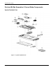
Illustrated Parts Catalog ProLiant BL20p Generation 3 Server Blade Components System Exploded View Figure 1-1: System exploded view 1-2 HP ProLiant BL20p Generation 3 Server Blade Maintenance and Service Guide
Illustrated Parts Catalog Server Blade Spare Parts List Table 1-1: Server Blade Spare Parts List Item Description Spare Part Number Mechanical Components 1 Access panel 371709-001 2 Hard drive blank 122759-001 Boards 3 Power button/LED board kit with LED cable (cable not shown *) 371706-001 4 SCSI backplane with cables (cables not shown *) 371701-001 5 System board with heatsinks a) System board for single-core processors 371700-001 b) System board for dual-core processors * 409353-001
Illustrated Parts Catalog Table 1-1: Server Blade Spare Parts List continued Item Description Spare Part Number a) Bezel assembly — b) Ejector latch assembly — c) Quarter-turn standoffs (2) — d) Rear power connector thumbscrews (2) — 15 Replacement battery, 3-V lithium * 234556-001 16 Server blade return kit * 237582-001 17 Local I/O cable* 355935-001 Memory 18 DIMM, 512-MB, ECC registered PC2-3200 DDR SDRAM * ** 359241-001 19 DIMM, 1-GB, ECC registered PC2-3200 DDR SDRAM * ** 3592
2 Removal and Replacement Procedures This chapter provides subassembly/module-level removal and replacement procedures for system components. After completing all necessary removal and replacement procedures, verify that all components operate properly by running the appropriate diagnostic software: • • For server blade components, run the Server Diagnostics Utility, available at www.hp.com. For server blade enclosure and power enclosure components, run the infrastructure diagnostics.
Removal and Replacement Procedures WARNING: To reduce the risk of injury from high-current electrical energy, do not remove the server blade access panel when power is applied through the HP ProLiant p-Class diagnostic station. Remove all power from the server blade before removing the access panel. WARNING: Setting the server blade power button to the standby position removes power from most areas of the server blade.
Removal and Replacement Procedures WARNING: To reduce the risk of personal injury or damage to the equipment, at least two people are needed to safely unload the rack from the pallet. An empty 42U rack weighs 115 kg (253 lb), is over 2.1 m (7 ft) tall, and may become unstable when being moved on its casters. Do not stand in front of the rack as it rolls down the ramp from the pallet, but handle the rack from both sides.
Removal and Replacement Procedures Server Blade Components Use the procedures in this section to perform service events on ProLiant BL20p G3 server blades. NOTE: Slate blue denotes serviceable parts, and port denotes hot-pluggable parts. Server Blade Preparation To service any internal server blade component, power down the server blade and remove it from the server blade enclosure. CAUTION: Electrostatic discharge can damage electronic components.
Removal and Replacement Procedures To service internal server blade components: 1. Identify the proper server blade in the server blade enclosure. 2. Remove power from the server blade in one of the following ways: — Use the Virtual Power Button feature in the iLO Remote Console to power down the server blade from a remote location. Be sure that the server blade is in standby mode by observing that the power LED is amber. — Press the power button on the front of the server blade.
Removal and Replacement Procedures 3. Remove the server blade from the server blade enclosure: a. Press the release button (1). CAUTION: After you press the release button, the server blade is unlocked from the enclosure. Use both hands to support the server blade when you remove it from the rack. b. Open the lever (2). c. Grasp the lever and slide the server blade from the enclosure (3). Place a hand under the server blade to support it as you remove it from the enclosure.
Removal and Replacement Procedures Access Panel To remove the access panel: 1. Power down the server blade and remove it from the server blade enclosure. Refer to the “Server Blade Preparation” section in this chapter. 2. Loosen the thumbscrew (1). 3. Press down on the thumb indentations, slide the access panel toward the rear of the unit about 1.25 cm (0.5 in), and lift to remove the panel (2). Figure 2-3: Removing the server blade access panel To replace the component, reverse the removal procedure.
Removal and Replacement Procedures Hard Drive Blanks To remove a hard drive blank: 1. Press the release buttons simultaneously (1). 2. Pull the blank out of the drive bay (2). Figure 2-4: Removing a hard drive blank CAUTION: Always populate hard drive bays with either a hot-plug SCSI hard drive or hard drive blank. Operating the server blade without a hot-plug SCSI hard drive or hard drive blank results in improper airflow and improper cooling that can lead to thermal damage.
Removal and Replacement Procedures Hot-Plug SCSI Hard Drives To assess hard drive status, observe the hot-plug SCSI hard drive status LEDs. For a detailed explanation of these LEDs, refer to Chapter 4, “Connectors, LEDs, and Switches.” CAUTION: Refer to the HP ProLiant Servers Troubleshooting Guide before removing a hard drive. IMPORTANT: It is not necessary to power down the server blade before removing or replacing a hot-plug SCSI hard drive. To remove a hot-plug SCSI hard drive: 1.
Removal and Replacement Procedures DIMMs To remove a DIMM: 1. Power down the server blade and remove it from the server blade enclosure. Refer to the “Server Blade Preparation” section in this chapter. 2. Remove the access panel. Refer to the “Access Panel” section in this chapter. NOTE: The server blade ships with at least two DIMMs installed in slots 1A and 2A. 3. Open the DIMM slot latches (1). 4. Remove the DIMM from the slot (2).
Removal and Replacement Procedures Processors and Heatsinks To remove a processor: 1. Power down the server blade and remove it from the server blade enclosure. Refer to “Server Blade Preparation” in this chapter. 2. Remove the access panel. Refer to “Access Panel” in this chapter. 3. Push down on the slate-blue heatsink locking levers on both sides of the heatsink and then pull them out and up (1). CAUTION: The heatsink is not reusable and must be discarded if removed from the processor after application.
Removal and Replacement Procedures 5. Raise the processor locking lever to release the processor (1) and remove the processor (2). Figure 2-8: Removing the processor To replace the processor: CAUTION: When installing the processor into the socket, be sure that the locking lever is raised to avoid damaging pins.
Removal and Replacement Procedures 1. With the processor locking lever raised, insert the processor with the edges properly aligned (1). 2. Lower the processor locking lever (2). Figure 2-9: Installing the processor 3. Remove the thermal interface media cover from the new heatsink. Figure 2-10: Removing the thermal interface media cover CAUTION: After the cover is removed, do not touch the thermal interface media. Touching the thermal interface media could cause processor overheating.
Removal and Replacement Procedures 4. Install the heatsink (1) and close the heatsink locking levers (2). CAUTION: The heatsink is not reusable and must be discarded if removed from the processor after application. Figure 2-11: Installing the heatsink Smart Array 6i Controller To remove the Smart Array 6i Controller: 1. Power down the server blade and remove it from the server blade enclosure. Refer to the “Server Blade Preparation” section in this chapter. 2. Remove the access panel.
Removal and Replacement Procedures 3. Turn the standoffs one quarter-turn (1). 4. Remove the Smart Array 6i Controller from the server blade (2). CAUTION: Disconnecting the battery module will cause any unsaved data in the memory module to be lost. Figure 2-12: Remove the Smart Array 6i Controller To replace the component, reverse the removal procedure.
Removal and Replacement Procedures Smart Array 6i 128-MB Battery Backed Write Cache Enabler To remove the 128-MB Battery-Backed Write Cache Enabler: 1. Power down the server blade and remove it from the server blade enclosure. Refer to the “Server Blade Preparation” section in this chapter. 2. Remove the access panel. Refer to the “Access Panel” section in this chapter. 3. Remove the Smart Array 6i Controller from the server blade. Refer to the “Smart Array 6i Controller” section in this chapter.
Removal and Replacement Procedures Fan Assembly To remove the fan assembly: 1. Power down the server blade and remove it from the server blade enclosure. Refer to the “Server Blade Preparation” section in this chapter. 2. Remove the access panel. Refer to the “Access Panel” section in this chapter. 3. Disconnect the fan assembly cables from the system board. IMPORTANT: Be sure to connect the cables to the same connectors when replacing the fan assembly.
Removal and Replacement Procedures 4. Press the fan retention tab (1) and lift up the assembly (2). Figure 2-16: Removing a fan assembly To replace the component, reverse the removal procedure. If the air baffle becomes loose, reverse the procedure in step 6 of “SCSI Backplane” in this chapter to reinstall the air baffle.
Removal and Replacement Procedures 3. Open the retaining latches (1). 4. Lift the FC adapter away from the system board (2). Figure 2-17: Removing the FC adapter To replace the component, reverse the removal procedure. Standard NIC Mezzanine Card To remove the standard NIC mezzanine card: 1. Power down the server blade and remove it from the server blade enclosure. Refer to the “Server Blade Preparation” section in this chapter. 2. Remove the access panel.
Removal and Replacement Procedures 4. Turn the quarter-turn standoff latches on the standard NIC mezzanine card counterclockwise (1). 5. Open the retaining latch (2) and lift the standard NIC mezzanine card away from the system board (3). CAUTION: Be sure to lift the board straight up. Lifting one edge of the board at a time may damage the connectors. Figure 2-18: Removing the standard NIC mezzanine card To replace the component, reverse the removal procedure.
Removal and Replacement Procedures 6. Remove the plastic air baffle (1)(2). 7. Disconnect the SCSI backplane signal cable from the system board (3). CAUTION: Be sure the LED board cable is not disengaged when removing the fan baffle. When reinstalling the fan baffle, be sure cable is fully seated. NOTE: The fan baffle is most easily removed at a 45˚ angle.
Removal and Replacement Procedures 8. Grasp the SCSI backplane on the left side when facing the rear of the server blade and lift slightly to rotate the SCSI backplane out (1). 9. Lift the SCSI backplane out of the chassis (2). Figure 2-20: Removing the SCSI backplane To replace the component, reverse the removal procedure. Power Converter Module To remove the power converter module: 1. Power down the server blade and remove it from the server blade enclosure.
Removal and Replacement Procedures 3. Disengage the thumbscrews (1) and remove the power converter modules (2). 4. Remove the power converter module retainers from the power converter module pair (2) and store for use on the new power converter module. NOTE: The server requires two power converter modules installed one on top of the other. The power converter modules may separate during removal or installation, be sure to align the modules and press together before installing on the system board.
Removal and Replacement Procedures 3. Remove the thumbscrews on the back of the chassis to release the power connector (1). NOTE: The power connector will not push completely into the chassis until the DC filter module is removed. It may be necessary to push in the power connector while removing the DC filter module. 4. Release the latches (2) and lift the DC filter module away from the system board (3) while pushing the power connector into the chassis (4).
Removal and Replacement Procedures 4. With a T-6 Torx screwdriver, remove the two retaining screws from the bottom of the chassis (1). 5. Disconnect the power button/LED cable from the back left side of the power button/LED board. 6. Slide the power button/LED board toward the left outside edge of the chassis (2). Figure 2-23: Removing the power button/LED retaining screws 7. Tilt the front edge of the power button/LED board down until the keyholes on the rear of the board clear the alignment pins (1).
Removal and Replacement Procedures IMPORTANT: Be sure the tab at the end of the power button/LED cable is inserted under the power button/LED board bezel. To replace the component, reverse the removal procedure. Battery If the server blade no longer automatically displays the correct date and time, you may need to replace the battery that provides power to the real-time clock. Under normal use, battery life is 5 to 10 years.
Removal and Replacement Procedures 4. Remove the existing battery by pushing the tab aside (1) and pulling the battery straight up (2). Figure 2-25: Opening the battery retaining clip To install the system board battery, push it into the socket until the tab locks in place.
Removal and Replacement Procedures System Board To remove the system board: 1. Power down the server blade and remove it from the server blade enclosure. Refer to the “Server Blade Preparation” section in this chapter. 2. Remove the access panel. Refer to the “Access Panel” section in this chapter. 3. Remove the DIMMs. Refer to the “DIMMs” section in this chapter. 4. Remove the processor and heatsinks. Refer to the “Processors and Heatsinks” section in this chapter. 5. Remove the fan assembly.
Removal and Replacement Procedures 13. Identify the keyhole locations and slide the system board toward the front of the server blade. IMPORTANT: The LED cable should be disconnected from the system board before removing the system board from the server blade. 14. Lift the system board until it comes off the alignment keys.
Removal and Replacement Procedures 15. Lift the edge of the system board nearest the system switches. The edge of the system board nearest the Smart Array 6i Controller connectors tilts down into the chassis, and the edge of the system board nearest the system switches tilts up out of the chassis. If necessary, refer to Figure 2-28 for the component locations. 16. Lift the system board out of the chassis. Figure 2-28: Removing the system board To replace the system board, reverse the removal procedure.
Removal and Replacement Procedures Server Blade Blanks To remove a server blade blank: 1. Press the release buttons simultaneously (1). 2. Slide the server blade blank from the server blade enclosure (2). Figure 2-29: Removing a server blade blank CAUTION: Always populate server blade enclosure bays with either a server blade or server blade blank. Operating the enclosure without a server blade or server blade blank results in improper airflow and improper cooling that can lead to thermal damage.
3 Diagnostic Tools ProLiant BL p-Class Diagnostic Tools Use the following tools to diagnose problems, test hardware, and monitor and manage system operations. Table 3-1: Diagnostic Tools Tool Description How to run the tool Array Diagnostics Utility (ADU) ADU is designed to run on all HP systems that support HP array controllers. ADU collects information about the array controllers in the system and generates a list of detected problems.
Diagnostic Tools Table 3-1: Diagnostic Tools continued Tool Description How to run the tool ROMPaq Utility The ROMPaq Utility checks the system and provides a choice of available ROM revisions and controller firmware. You can download this utility from the HP website: Survey Utility gathers critical hardware and software information on server blades.
Diagnostic Tools HP ProLiant Essentials Rapid Deployment Pack (RDP) The optional HP ProLiant Essentials RDP is the preferred method for rapid, high-volume server blade deployments. The RDP includes Altiris eXpress Deployment Server and the SmartStart Scripting Toolkit. Install the CD in the CD-ROM drive of the administrator workstation or client PC and refer to the documentation that ships with the software. ROM-Based Setup Utility (RBSU) RBSU configures the hardware installed in the server blade.
4 Connectors, LEDs, and Switches Connectors ProLiant BL20p Generation 3 Server Blade Front Panel Connectors The server blade has one front panel connector, a port that accepts the local I/O cable, for configuration and troubleshooting purposes. Figure 4-1: ProLiant BL20p G3 I/O port CAUTION: Disconnect the local I/O cable from the port when not in use. The port and connector do not provide a permanent connection.
Connectors, LEDs, and Switches Rear Panel Connectors Use Figure 4-2 and Table 4-1 to identify ProLiant BL20p G3 server blade rear panel connectors.
Connectors, LEDs, and Switches System Board Components and Connectors Use Figure 4-3 and Table 4-2 to identify ProLiant BL20p G3 system board components and connectors.
Connectors, LEDs, and Switches Table 4-2: System Board Components and Connectors Item Description 1 Power button/LED board connector 2 SCSI backplane board connector 1 3 Processor socket 2 4 Smart Array 6i Controller 5 Standard NIC Mezzanine card 6 Smart Array 6i 128-MB Battery-Backed Write Cache Enabler (Optional) 7 Power converter module 8 HP ProLiant BL20p G3 Fibre Channel adapter 9 DC filter module 10 DIMM slots (4) 11 System Battery 12 Processor socket 1 (populated) 13 SCSI
Connectors, LEDs, and Switches Figure 4-4: Local I/O cable connectors Table 4-3: Local I/O Cable Connectors Item Description 1 Server blade connector 2 Video connector 3 USB connector 1 4 USB connector 2 5 Serial connector 6 iLO RJ-45 (10/100 Ethernet) connector HP ProLiant BL20p Generation 3 Server Blade Maintenance and Service Guide 4-5
Connectors, LEDs, and Switches LEDs Use the following section to identify LEDs on the following ProLiant BL p-Class system components: • ProLiant BL20p G3 server blade front panel • Hot-plug SCSI hard drives ProLiant BL20p Generation 3 Server Blade Front Panel Seven LEDs on the front of the server blade indicate server status. Use Figure 4-5 and Table 4-4 to identify LED locations and functions.
Connectors, LEDs, and Switches Table 4-4: ProLiant BL20p G3 Server Blade Front Panel LEDs Item LED Description Status 1 Unit identification Blue = Flagged Blue flashing = Management mode Off = No remote management 2 Health Green = Normal status Flashing = Booting Amber = Degraded status Red = Critical status 3 NIC 1 * Green = Linked to network 4 NIC 2 * Green flashing = Network activity 5 NIC 3 * Off = No activity 6 NIC 4 * 7 Power Green = On Amber = Standby (power available) Off = Un
Connectors, LEDs, and Switches Figure 4-6: Hot-plug SCSI hard drive LEDs Table 4-5: Hot-Plug SCSI Hard Drive LEDs 1 Activity 2 Online 3 Fault Means On Off Off Do not remove the drive. Removing a drive during this process causes data loss. The drive is being accessed and is not configured as part of an array. On Flashing Off Do not remove the drive. Removing a drive during this process causes data loss. The drive is rebuilding or undergoing capacity expansion.
Connectors, LEDs, and Switches Table 4-5: Hot-Plug SCSI Hard Drive LEDs continued 1 Activity 2 Online 3 Fault Means Off Off On OK to replace the drive online. The drive has failed and has been placed offline. Off On Off OK to replace the drive online if a predictive failure alert is received, provided that the array is configured for fault tolerance and all other drives in the array are online. The drive is online and configured as part of an array.
Connectors, LEDs, and Switches Buttons and Switches Use the following sections to identify the locations and functions of push-button and system switches. Buttons Use the “Power Button” section to identify push-button switches on the system hardware. Power Button Setting the server blade power button to the standby position removes power from most areas of the server blade. This process may take 30 seconds, during which time some internal circuitry remains active.
Connectors, LEDs, and Switches Switches System switches enable you to change certain settings or to perform advanced diagnostic procedures. The following sections explain the functions of each switch. Use Figure 4-8 and Table 4-6 to identify switch locations and functions.
Connectors, LEDs, and Switches NMI Switch Crash dump analysis is an essential part of eliminating reliability problems such as hangs or crashes in operating systems, device drivers, and applications. Crashes can freeze a system, requiring you to do a hard reset. Resetting the system erases any information that supports root cause analysis. Systems running Microsoft Windows 2000 experience a blue-screen trap when the operating system crashes.
Connectors, LEDs, and Switches 7. Power up the server blade: — Press the power button on the front of the server blade. — Use the virtual power button feature in the iLO remote console. 8. Wait for the POST message that prompts you to change the switch setting: Maintenance switch detected in the "On" position. Power off the server and turn switch to the "Off" position. 9. Repeat steps 1 through 3. 10. Change position 6 of SW2 to off. 11. Repeat steps 5 through 7.
Connectors, LEDs, and Switches 9. Repeat steps 1 through 3. 10. Change positions 1, 5, and 6 of SW2 to off. 11. Repeat steps 5 through 7. If both the current and backup versions of the ROM are corrupt, you must return the system board for a service replacement. For spare part numbers, refer to Chapter 1, “Illustrated Parts Catalog.
5 Server Blade Specifications This chapter provides operating and performance specifications for the ProLiant BL20p G3 server blade. HP ProLiant BL20p Generation 3 Server Blade Table 5-1: Operating and Performance Specifications for the ProLiant BL20p G3 Server Blade Dimensions Width 26.14 cm (10.29 in) Depth 71.1 cm (28.00 in) Height 4.29 cm (1.69 in) Weight (maximum) Temperature range 9.43 kg (20.
Index 1 128-MB Battery-Backed Write Cache Enabler removing 2-16 replacing 2-16 spare part number 1-4 A access panel removing 2-7 replacing 2-7 spare part number 1-3 ADU See Array Diagnostics Utility (ADU) alignment keys 2-30 Array Diagnostics Utility (ADU) access 3-1 description 3-1 ASR-2 See Automatic Server Recovery-2 (ASR-2) Automatic Server Recovery-2 (ASR-2) access 3-1 description 3-1 B battery disposal 2-26 disposal, caution 2-26 location 4-4 removing 2-26 replacing 2-27 spare part number 1-4 warni
Index guides HP ProLiant BL p-Class System Setup and Installation Guide 3-1 HP ProLiant Servers Troubleshooting Guide 3-1 H hard drive blank removing 2-8 replacing 2-8 spare part number 1-3 heatsink, spare part number 1-3 help resources vii hot surfaces, warning 2-3 hot-plug SCSI hard drives LEDs 4-7 removing 2-9 replacing 2-9 HP ProLiant BL p-Class System Setup and Installation Guide 3-1 HP ProLiant BL30p dual port Fibre Channel adapter 2-18 HP ProLiant BL30p Fibre Channel adapter, location 4-4 HP ProLia
Index access 3-2 description 3-2 R rack cautions 2-2 warnings 2-2 weight 2-3 RBSU See ROM-Based Setup Utility redundant ROM, accessing 4-13 removing 128-MB Battery-Backed Write Cache Enabler 2-16 access panel 2-7 battery 2-26 DC filter module 2-23 DIMMs 2-10 fan assembly 2-17 FC adapter 2-18 hard drive blank 2-8 hot-plug SCSI hard drives 2-9 power button/LED board 2-24 power converter module 2-22 processor 2-11 SCSI backplane 2-20, 2-22 server blade blank 2-31 server blades 2-6 Smart Array 6i controller
Index replacing 2-30 spare part number 1-3 system switches, server blade 4-11 Integrated Lights-Out ROM-Based Setup Utility (iLO RBSU) 3-2 Option ROM Configuration for Arrays (ORCA) 3-2 RBSU 3-3 ROMPaq 3-2 Survey Utility 3-2 T technician notes v transceiver, spare part number 1-4 V U unit identification (UID), LEDs 4-7 utilities Diagnostics 3-1 HP ProLiant Essentials Rapid Deployment Pack 3-3 HP Systems Insight Manager 3-1 Index-4 ventilation clearances vi W warranty vi HP ProLiant BL20p Generation