HP ProLiant BladeSystem p-Class System Maintenance and Service Guide Part number: 230856-008 Eighth edition: June 2006
Legal notices © Copyright 2004-2006 Hewlett-Packard Development Company, L.P. The information contained herein is subject to change without notice. The only warranties for HP products and services are set forth in the express warranty statements accompanying such products and services. Nothing herein should be construed as constituting an additional warranty. HP shall not be liable for technical or editorial errors or omissions contained herein. Microsoft and Windows are U.S.
Contents Revision history Revision tables....................................................................................................................................... 10 About This Guide Technician Notes ................................................................................................................................... 11 Where to Go for Additional Help.............................................................................................................
HP BladeSystem p-Class 3U Power Enclosure Power Management Module ............................................... 48 HP BladeSystem p-Class 3U Power Enclosure........................................................................................ 48 Power Distribution Components ............................................................................................................... 49 Scalable or Mini Bus Bars ...........................................................................................
North America/Japan ..................................................................................................................... 113 International ................................................................................................................................... 115 Hot-Plug Power Supply.......................................................................................................................... 116 Power Distribution Devices .............................................
Figures Figure Figure Figure Figure Figure Figure Figure Figure Figure Figure Figure Figure Figure Figure Figure Figure Figure Figure Figure Figure Figure Figure Figure Figure Figure Figure Figure Figure Figure Figure Figure Figure Figure Figure Figure Figure Figure Figure Figure Figure Figure Figure Figure Figure Figure Figure Figure Figure Figure Figure Figure Figure Figure Figure 1-1 Server blade enclosure components with enhanced backplane components – exploded view ................
Figure Figure Figure Figure Figure Figure Figure Figure Figure Figure Figure Figure Figure Figure Figure Figure Figure Figure Figure Figure Figure Figure Figure Figure Figure Figure Figure Figure Figure Figure Figure Figure Figure Figure Figure Figure Figure Figure Figure Figure Figure Figure Figure Figure Figure Figure Figure Figure Figure Figure Figure Figure Figure Figure Figure Figure Figure 2-46 Disconnecting cables from the power bus box ...............................................................
Figure 4-46 Power configuration switches .................................................................................................... 105 Figure 4-47 Power zones in a full-rack 42U solution ...................................................................................... 106 Figure 4-48 CGESM switch module buttons..................................................................................................
Table 4-42 Diagnostic Station LEDs ............................................................................................................ 101 Table 4-43 Reset and Unit Identification Buttons ........................................................................................... 103 Table 4-44 Dynamic Power Saver Configuation Switches .............................................................................. 104 Table 4-45 Power Configuration Switches ...........................................
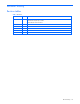
Revision history Revision tables Table 1 Revisions Date Edition Revision June 2006 8 Updated Technical Support section with correct contact information Added ROHS-compliant part numbers Added CGESM switch information Revision history 10
About This Guide This maintenance and service guide can be used for reference when servicing HP BladeSystem p-Class systems. WARNING! To reduce the risk of personal injury from electric shock and hazardous energy levels, only authorized service technicians should attempt to repair this equipment. Improper repairs can create conditions that are hazardous. Technician Notes WARNING! Only authorized technicians trained by HP should attempt to repair this equipment.
• White paper: Configuring a Preboot eXecution Environment (PXE) using Red Hat Linux 7.2 on HP ProLiant Servers • QuickSpecs • Service Quick Reference Guide • Service training guides • HP service advisories and bulletins • QuickFind information services • HP Systems Insight Manager (HP SIM) software For additional information or copies of these documents, visit the HP website (http://www.hp.com).
1 Illustrated Parts Catalog This chapter provides illustrated parts and spare parts lists for the HP BladeSystem p-Class system components. Refer to Table 1-1 through Table 1-6 for the names of referenced spare parts.
HP BladeSystem p-Class Server Blade Enclosure Components Server Blade Enclosure Components with Enhanced Backplane Components — Exploded View Figure 1-1 Server blade enclosure components with enhanced backplane components – exploded view Illustrated Parts Catalog 14
Server Blade Enclosure Components — Exploded View Figure 1-2 Server blade enclosure components – exploded view Illustrated Parts Catalog 15
Server Blade Enclosure Spare Parts List Table 1-1 Server Blade Enclosure Spare Parts List Item Description Original Spare Part Number Modified Spare Part Number Mechanical Components 1 Server blade enclosure — — 2 ProLiant BL30p blade sleeve 1 — — Blade sleeve access panel * 361881-001 — 3 Server blade blank (half-height) Part of kit 361750-001 — 4 Server blade blank (full-height) 270462-001 — Enhanced Backplane Components 1 5a Power backplane assembly 357905-001‡ See requirement 4
HP BladeSystem p-Class Interconnect Components RJ-45 Patch Panel — Exploded View Figure 1-3 RJ-45 patch panel — exploded view Illustrated Parts Catalog 17
GbE Interconnect Switch and GbE2 Interconnect Switch — Exploded View Figure 1-4 GbE Interconnect Switch and GbE2 Interconnect Switch — exploded view Illustrated Parts Catalog 18
HP BladeSystem p-Class Interconnect Spare Parts List Table 1-2 HP BladeSystem p-Class Interconnect Spare Parts List Item Description Original Spare Part Number Modified Spare Part Number ProLiant BL p-Class RJ-45 Patch Panels 1 RJ-45 patch panel 253236-001 — 2 RJ-45 patch panel 2, with Fibre Channel Support * 322299-001 — 3 Patch panel RJ-45 module, 10-connector 253240-001 — 4 Patch panel RJ-45 module, 6-connector 253241-001 — ProLiant BL p-Class GbE Interconnect Switch 5 GbE Interconne
Power Enclosure Components HP BladeSystem p-Class 1U Power Enclosure — Exploded View Figure 1-5 HP BladeSystem p-Class 1U power enclosure — exploded view Illustrated Parts Catalog 20
HP BladeSystem p-Class 1U Power Enclosure Spare Parts List Table 1-3 HP BladeSystem p-Class 1U Power Enclosure Spare Parts List Item Description Original Spare Part Number Modified Spare Part Number 1 Power enclosure chassis (shown for reference only) — — 2 Plastics kit, miscellaneous:* Blank, power supply Thumbscrew covers* 384782-001‡ See requirement 409741-001 3 Power supply, 2000W, 1U 384779-001 — 4 Module, power management 384781-001‡ See requirement 409744-001 5 Board, backplane,
HP BladeSystem p-Class 3U Power Enclosure — Exploded View Figure 1-6 HP BladeSystem p-Class 3U power enclosure — exploded view (cables removed for clarity) Illustrated Parts Catalog 22
HP BladeSystem p-Class 3U Power Enclosure Spare Parts List Table 1-4 HP BladeSystem p-Class 3U Power Enclosure Spare Parts List Item Description Original Spare Part Number Modified Spare Part Number 1 Power enclosure, chassis with backplane and power cords — — a) North American/Japanese single-phase 274840-001 — b) North American/Japanese three-phase* 274841-001 — c) International single-phase * 274842-001 — d) International three-phase * 274843-001 — 2 Power supply blank 274844-001 —
Power Distribution Components Power Bus Bar Components — Exploded View Figure 1-7 Power bus bar components — exploded view (bus bar cables and couplers removed for clarity) Illustrated Parts Catalog 24
Figure 1-8 Power distribution components — exploded view Illustrated Parts Catalog 25
Power Distribution Components Spare Parts List Table 1-5 Power Distribution Components Spare Parts List Item Description Original Spare Part Number Modified Spare Part Number System Components 1 Scalable bus bar A 270460-001 — 2 Scalable bus bar B 270459-001 — 3 Mini bus bar A — — 4 Mini bus bar B 270457-001 — 5 Power bus box (with A and B labels) 270461-001 — Facility DC Power 6 Scalable bus bar grounding cable Part of kit 270465-001 — 7 Mini bus bar grounding cable Part of ki
Diagnostic Station Components Diagnostic Station — Exploded View Figure 1-9 Diagnostic station — exploded view Illustrated Parts Catalog 27
Diagnostic Station Spare Parts List Table 1-6 Diagnostic Station Spare Parts List Item Description Original Spare Part Number Modified Spare Part Number 1 VHDM converter 257875-001 — 2 Power supply 164460-001 — 3 System board 257874-001 — Cable kit * 257873-001 — AC power cord — — DC power cord for server blade — — DC power cord for interconnect switch — — Data transfer cable — — Network cable with RJ-45 connectors — — Diagnostic cable — — 5 Plastics kit * 257871-001
2 Removal and Replacement Procedures This chapter provides subassembly/module-level removal and replacement procedures for system components. After completing all necessary removal and replacement procedures, verify that all components operate properly by running the appropriate diagnostic software: • For server blade components, run the Server Diagnostics utility, available from the HP website (http://www.hp.com).
WARNING! Always use at least two people to lift a power supply enclosure or server blade enclosure into the rack. If the enclosure is being loaded into the rack above chest level, a third person MUST assist with aligning the enclosure with the rails while the other two people support the weight of the enclosure. WARNING! To reduce the risk of personal injury or damage to the equipment, be sure that: • The leveling jacks of the rack are extended to the floor.
WARNING! Be sure that power is not applied to the Mini Bus Bar Dual Power Box power cables before connecting to or disconnecting from the power supply. Disconnect all AC power cords from the power source. WARNING! Be sure that all power enclosure circuit breakers are locked in the off position before connecting or disconnecting any power components.
a. Remove power from the facility power connection. b. Disconnect the PDU jumper cords from the power enclosure. 4. If the server blade enclosure is powered from a 3U power enclosure, remove power from the bus bar or power bus box couplers (both A and B) connected to the server blade enclosure: a. Unlock the circuit breakers switches (1). b. Set the switches to the off position (2). c. Lock the switches in the off position (3).
Figure 2-3 Removing a server blade blank CAUTION: Always populate server blade enclosure bays with either a server blade or server blade blank. Operating the enclosure without a server blade or server blade blank results in improper airflow and improper cooling that can lead to thermal damage. To replace a server blade blank, align the blank with the empty bay and slide it in until the blank is fully seated.
1. Remove the interconnect switch. Refer to the “RJ-45 Patch Panels and Interconnect Switches” section in this chapter. 2. Remove the GbE2 Interconnect Switch cover. Figure 2-5 Removing the GbE2 Interconnect Switch cover 3. Remove the Fibre Channel signal-conditioning card. Figure 2-6 Removing the Fibre Channel signal-conditioning card Reverse steps 1 through 3 to replace the Fibre Channel signal-conditioning card.
1. Press the module release lever (1). 2. Slide the patch panel RJ-45 module or interconnect module out of the RJ-45 patch panel or interconnect switch (2). 3. Disconnect the network cables (3). Figure 2-7 Removing a patch panel RJ-45 module or interconnect module Reverse steps 1 through 3 to replace a patch panel RJ-45 module or interconnect module. Enhanced Server Blade Enclosure Backplane Components Server Blade Management Module To remove the server blade management module: 1.
1. Align the server management module with the metal guide tabs on the signal backplane. 2. Press the module into place. 3. Tighten the thumbscrew to fully seat the connectors. 4. Install the management module cabling. Refer to the HP ProLiant p-Class Server Blade Enclosure Installation Guide. Signal Backplane To remove the signal backplane: 1. Power down the server blade enclosure. Refer to the “Server Blade Enclosure Preparation” section in this chapter. 2.
Figure 2-10 Removing a signal backplane IMPORTANT: The replacement part ships with a protective cover on the VHDM connectors. Remove this cover before installing the new part. Reverse steps 1 through 9 to replace the signal backplane. Power Backplane Assembly WARNING! To reduce the risk of injury from hot surfaces, allow external components to cool before servicing them. To remove the power backplane assembly: 1. 2. Power down the server blade enclosure.
Figure 2-11 Disconnecting signal backplane power cable 6. Loosen the three thumbscrews (1). 7. Pull the power backplane assembly away from the chassis (2). Figure 2-12 Removing a power backplane assembly Reverse steps 1 through 7 to replace the power backplane assembly. Standard Server Blade Enclosure Backplane Components Server Blade Management Module To remove the server blade management module: 1. Disconnect any management cables connected to the server blade management module.
Figure 2-13 Removing a server blade management module To replace the server blade management module: 1. Align the module with its connector and the metal guiding tabs on the server blade enclosure. 2. Slide the module to the left to insert it into the connector until it is fully seated. 3. Install the management module cabling. Refer to the HP BladeSystem p-Class System Setup and Installation Guide. Signal Backplane To remove the signal backplane: 1. 2. Power down the server blade enclosure.
Figure 2-14 Disconnecting signal and power backplane cables 8. Loosen the three thumbscrews (1). 9. Disengage the locking pins (2). 10. Pull the signal backplane away from the chassis (3). Figure 2-15 Removing a signal backplane IMPORTANT: The replacement part ships with a protective cover on the VHDM connectors. Remove this cover before installing the new part. Reverse steps 1 through 10 to replace the signal backplane.
2. Unseat the server blades from the power backplane assembly by sliding them approximately 2.54 cm (1 in) out of the server blade enclosure. Refer to the documentation shipped with the server blades. 3. Disconnect the server blade management module signal cable from the power backplane assembly (1). 4. Disconnect the power backplane cable from the signal backplane (2). Figure 2-16 Disconnecting signal and power backplane cables 5. Loosen the three thumbscrews (1). 6.
3. Power down the server blade enclosure. Refer to the “Server Blade Enclosure Preparation” section in this chapter. NOTE: If you are only removing the server blade enclosure to service its non-hot-plug components, server blade blanks can remain installed. 4. Remove both RJ-45 patch panels or interconnect switches. Refer to the “RJ-45 Patch Panels and Interconnect Switches” section in this chapter. 5. Remove all interconnect modules.
CAUTION: Each power enclosure has two or more power supply cords. A single rack or cabinet may contain more than one power enclosure. Power may be supplied in a redundant fashion. Removing any single source of power does not necessarily remove power from any portion of the system. When performing any service other than hot-plug module replacement, you must completely disconnect all power to that portion of the system.
Figure 2-20 Removing an HP BladeSystem p-Class 1U Power Supply Blank To replace a power supply blank, slide the power supply blank into the bay until it seats. HP BladeSystem p-Class 1U Power Supply To remove a power supply: 1. Press the release buttons simultaneously. 2. Pull the power supply out of the enclosure. Figure 2-21 Removing a 1U Power Supply To replace a power supply, slide the power supply into the bay until it seats.
Figure 2-22 Removing the 1U power management module Reverse steps 1 through 3 to replace the power management module. HP BladeSystem p-Class 1U Power Enclosure To remove a power enclosure: 1. Remove power from the AC Power source. Refer to the “Power Components Preparation” section in this chapter. 2. Disconnect the PDU jumper cords from the power enclosure. 3. Disconnect the power enclosure DC output cables from the server blade enclosure. 4. Remove all hot-plug power supplies.
HP BladeSystem p-Class 1U Power Enclosure Backplane Board To remove the power backplane assembly: 1. Power down the system. Refer to the “Power Components Preparation” section in this chapter. 2. Remove the power management module. Refer to the “HP BladeSystem p-Class 1U Power Enclosure Power Management Module” section in this chapter. 3. Remove the power enclosure from the rack. Refer to the “HP BladeSystem p-Class 1U Power Enclosure” section in this chapter. 4.
To remove a power supply blank: 1. Press the release buttons simultaneously (1). 2. Pull the power supply blank out of the power enclosure (2). Figure 2-26 Removing a 3U power supply blank CAUTION: Always populate power supply bays with either a hot-plug power supply or power supply blank. Operating the enclosure without a hot-plug power supply or power supply blank results in improper airflow and improper cooling that can lead to thermal damage..
Figure 2-27 Removing a 3U hot-plug power supply To replace a hot-plug power supply, slide the hot-plug power supply into the bay and close the lever. HP BladeSystem p-Class 3U Power Enclosure Power Management Module To remove the power management module: 1. Disconnect any management cables connected to the module. NOTE: This component is hot-plug capable. 2. Loosen the thumbscrews (1). 3. Slide the module out of the power enclosure (2).
3. If you have bus bars, refer to steps 3 through 6 of the “Scalable or Mini Bus Bars” section in this chapter. 4. If you have power bus boxes, refer to steps 3 through 5 of the “Power Bus Box” section in this chapter. 5. Disconnect the load-balancing signal cable, if you have two power enclosures installed in a scalable bus bar configuration. 6. Remove the power management module. Refer to the “HP BladeSystem p-Class 3U Power Enclosure Power Management Module” section in this chapter. 7.
Figure 2-30 Disconnecting bus bar couplers from server blade enclosures 3. Remove the screws from the bus bar access cover (1). 4. Remove the access cover (2). NOTE: The access covers for mini bus bars are different from scalable bus bars. For an illustration of the mini bus bar access cover, refer to the “Mini and Scalable Bus Bars” section in Chapter 4, “Connectors, LEDs, and Switches.” 5. Remove the screw from the cable guide (3).
Figure 2-32 Disconnecting power cables 8. Use a 4 mm (5/32 in) hex wrench to loosen the hinge bolts securing the bus bar to the hinge (1). 9. Pull the hinge bolts out of the hinges (2). 10. Remove the bus bars from the hinges (3). Figure 2-33 Removing the hinge bolts and bus bars 11. Repeat steps 8 through 10 for the second bus bar, if you are replacing both bus bars. 12. Remove the screws securing the hinge to the rack (1). 13. Remove the hinges from the rack (2).
Figure 2-34 Removing the hinges from the rack Reverse steps 1 through 13 to replace the bus bars. Mini Bus Bar Dual Power Box WARNING! Be sure that power is not applied to the Dual Power Box power cables before connecting to the power enclosure. Disconnect all AC power cords from the power source. WARNING! Be sure that all power enclosure circuit breakers are locked in the off position before connecting any power components. To remove the Mini Bus Bar Dual Power Box(es): 1.
Figure 2-36 Removing cables from mini bus bar 3. Replace the mini bus bar cover. Figure 2-37 Replacing mini bus bar cover 4. Remove the cover from the Dual Power Box using a T-25 Torx screwdriver.
Figure 2-38 Removing Dual Power Box cover 5. Detach the Dual Power Box from the mini bus bar. Figure 2-39 Detach the Dual Power Box from mini bus bar 6. Remove the power cables.
Figure 2-40 Removing cables from the Dual Power Box 7. Replace the Dual Power Box cover using a T-25 Torx screwdriver. Figure 2-41 Replacing the Dual Power Box cover Repeat this procedure for the second mini bus bar. Reverse steps 1 through 7 to replace the mini bus bar dual power box. Power Bus Box To remove the power bus box: 1. Remove power from the power bus box. Refer to the “Power Components Preparation” section in this chapter. 2.
Figure 2-42 Disconnecting a power bus box coupler from a server blade enclosure 3. Remove the cable bracket from the rack: a. Loosen the thumbscrews (1). b. Pull the bracket away from the rack (2). Figure 2-43 Removing the cable bracket from the rack 4. Remove the power bus box from the cable bracket.
Figure 2-44 Removing the power bus box from the cable bracket 5. Remove the screws from the power bus box cover (1). 6. Remove the cover (2). Figure 2-45 Removing the power bus box cover 7. Disconnect the facility DC input cables or power enclosure DC output power cables.
Figure 2-46 Disconnecting cables from the power bus box Reverse steps 1 through 7 to replace the power bus box. Facility DC Power Cables To remove the facility DC power cables: 1. Remove power from the facility DC power cables. Refer to the “Power Components Preparation” section in this chapter. Be sure to disconnect the facility DC power cables from the facility connection. 2.
Figure 2-47 Powering down the diagnostic station 4. Remove the diagnostic station AC power cord from the AC outlet. 5. Disconnect the DC power cord from the diagnostic station. 6. Disconnect all data cables from the diagnostic station. 7. Place the diagnostic station on a flat, level surface. Reverse steps 1 through 7 to power up the diagnostic station. For full installation and cabling procedures, refer to the documentation that ships with the diagnostic station.
Figure 2-49 Removing the diagnostic station power supply Reverse steps 1 through 5 to replace the diagnostic station power supply. Diagnostic Station System Board To remove a diagnostic station system board: 1. Power down the diagnostic station. Refer to the “Diagnostic Station Preparation” section in this chapter. WARNING! To reduce the risk of shock or injury from high-current electrical energy, be sure to disconnect all AC power cords before performing service procedures. 2.
Figure 2-51 Removing the diagnostic station system board Reverse steps 1 through 3 to replace the diagnostic station system board.
3 Diagnostic Tools This chapter is an overview of software and firmware diagnostic tools that are available for configuring, monitoring, and managing the system. HP BladeSystem p-Class Diagnostic Tools Use the following tools to diagnose problems, test hardware, and monitor and manage system operations. Table 3-1 Diagnostic Tools Tool Description Array Diagnostics Utility (ADU) ADU is designed to run on all HP For a list of HP systems that support systems that support HP array controllers.
Table 3-1 Diagnostic Tools Tool Description How to run the tool Integrated Lights-Out ROM-Based Setup Utility (iLO RBSU) The iLO RBSU is the recommended Run iLO RBSU by pressing the F8 key method to configure and set up the iLO. during POST. The iLO RBSU is designed to assist you with setting up an iLO on a network; it is not intended for continued administration. Integrated Management Log (IML) The IML is a log of system events such as system failures or nonfatal error conditions.
• Gather fault information. • Re-populate chassis serial numbers following a backplane replacement. Connecting to the Service Port A connection to the service port requires a client PC with the minimum components: • Serial connector • Terminal software Also, locate the null-modem cable that ships with the bus bars or power bus boxes. To connect to the service port: 1. Connect the null-modem cable to the service port. Refer to Chapter 4, “Connectors, LEDs, and Switches,” for service port locations.
Server Blade Management Module This section describes diagnostic screens for the server blade management module. IMPORTANT: The screens in this section only provide information about the server blade enclosure to which you are connected. To run diagnostics and access information about different server blade enclosures, you must connect to the server blade management module on that enclosure.
Figure 3-2 Faults Page screen The Faults Page screen includes the following information: • Uptime • Location and description of fault codes • Number of faults (count) • Faults timestamp • Command legend Rack Status Screen To view the Rack Status screen, press the S key.
Figure 3-4 Set Enclosure Serial Number screen To set the enclosure serial number: 1. Type the new serial number. 2. Press the Enter key. 3. Type the new serial number again. 4. Reset all management modules in the rack for the changes to take effect. Power Management Module This section describes diagnostic screens for the power management module. IMPORTANT: The screens in this section only provide information about the power enclosure to which you are connected.
• Number of fault conditions • Status of unit identification (UID) LED • Status of enclosure link • Management module firmware version • Redundancy status • Command legend Redundant Status Screen To view the Redundant Status screen, press the R key.
4 Connectors, LEDs, and Switches This chapter explains the location and function of system connectors, internal and external LEDs, and switches.
Figure 4-1 Rear view of server blade enclosure (with enhanced backplane components) and power enclosure Figure 4-2 Rear view of server blade enclosure and power enclosure Table 4-1 Enclosure, Management Module, and Backplane Components Item Description 1 Server blade enclosure 2 Server blade management module 3 Server blade management module service port* 4 Server blade management link connectors (top to enclosure above, bottom to enclosure below) 5 DC power input connector for bus A 6 DC out
Table 4-1 Enclosure, Management Module, and Backplane Components Item Description 14 Load-balancing signal cable connector 15 Power enclosure 16 DC power input connector for bus B 17 Server blade management module iLO port * The service port enables qualified service personnel to run infrastructure diagnostics. Refer to Chapter 3, “Diagnostic Tools,” for more information.
Figure 4-4 and Table 4-3 identify the patch panel RJ-45 connectors corresponding to the BL20p G2 server blade network adapter Ethernet signals.
Table 4-4 Patch Panel RJ-45 Connectors for the BL30p Server Blade Item Enclosure Enclosure with Enhanced Backplanes B1–B16 N/A1 NC7781 10/100/1000T data NIC A1–A16 N/A NC7781 10/100/1000T data NIC2 1 BL30p series blades require server blade enclosures with enhanced backplane components. Refer to “Server Blade Enclosure Spare Parts List” in Chapter 1. 2 This is the default enabled PXE NIC. Using the ROM setup utility on the server, any other data NIC may be PXE enabled.
Table 4-5 Patch Panel RJ-45 Connectors for the BL40p Server Blades Item Enclosure Enclosure with Enhanced Backplanes Server Blade 1 B1 iLO 10/100T NIC Not used B2 NC7781 10/100/1000T data NIC NC7781 10/100/1000T data NIC B3 NC7781 10/100/1000T data NIC A1 NC7781 10/100/1000T data NIC A2 NC7781 10/100/1000T data NIC NC7781 10/100/1000T data NIC A3 NC7781 10/100/1000T data NIC NC7781 10/100/1000T data NIC 1 NC7781 10/100/1000T data NIC 2 NC7781 10/100/1000T data NIC 2 Server Blade 2 B4
Table 4-6 QuadT Interconnect Module RJ-45 Connectors Item Description 1 Port 22 RJ-45 connector for 10/100/1000Base-T uplink on switch B 2 Port 21 RJ-45 connector for 10/100/1000Base-T uplink on switch B 3 Port 20 RJ-45 connector for 10/100Base-T uplink on switch B 4 Port 19 RJ-45 connector for 10/100Base-T uplink on switch B 5 Port 22 RJ-45 connector for 10/100/1000Base-T uplink on switch A 6 Port 21 RJ-45 connector for 10/100/1000Base-T uplink on switch A 7 Port 20 RJ-45 connector for 10/10
Figure 4-9 QuadT2 interconnect module connectors NOTE: The QuadT2 interconnect module ships with the HP BladeSystem p-Class C-GbE2 Interconnect Kit.
Table 4-9 QuadSX Interconnect Module Connectors Item Description 1 Port 22 LC fiber connector for 1000SX uplink on switch B 2 Port 21 LC fiber connector for 1000SX uplink on switch B 3 Port 20 LC fiber connector for 1000SX uplink on switch B 4 Port 19 LC fiber connector for 1000SX uplink on switch B 5 Port 22 LC fiber connector for 1000SX uplink on switch A 6 Port 21 LC fiber connector for 1000SX uplink on switch A 7 Port 20 LC fiber connector for 1000SX uplink on switch A 8 Port 19 LC fibe
Table 4-10 OctalFC Interconnect Module Ports Item BL20p G2 BL30p* 1 FC port for server blade 1 FC port for server blade 1 and 9 2 FC port for server blade 2 FC port for server blade 2 and 10 3 FC port for server blade 3 FC port for server blade 3 and 11 4 FC port for server blade 4 FC port for server blade 4 and 12 5 FC port for server blade 5 FC port for server blade 5 and 13 6 FC port for server blade 6 FC port for server blade 6 and 14 7 FC port for server blade 7 FC port for serve
Figure 4-13 Rear panel SFP port numbering Table 4-12 SFP Module Ports Port Description 22 Port 22 SFP connector for 10/100/1000 Base-T copper or 1000 Base-SX fiber uplink 21 Port 21 SFP connector for 10/100/1000 Base-T copper or 1000 Base-SX fiber uplink 20 Port 20 SFP connector for 10/100/1000 Base-T copper or 1000 Base-SX fiber uplink 19 Port 19 SFP connector for 10/100/1000 Base-T copper or 1000 Base-SX fiber uplink Mini and Scalable Bus Bars Use Figure 4-14 and Table 4-13 to identify mini and
Figure 4-14 Scalable (shown left) and mini (shown right) bus bar components Table 4-13 Mini and Scalable Bus Bar Components Item Description 1 DC power output cables with couplers 2 DC circuit breakers 3 DC power input connector access 4 DC power input connector access cover 5 Mini Bus Bar Dual Power Box (not shown; for use with Mini Bus Bar only)* * Included in the Mini Bus Bar Dual Power Kit, this option enables the Mini Bus Bar to support two power enclosures.
Figure 4-15 Power bus box components (some internal pieces removed for clarity) Table 4-14 Power Bus Box Components Item Description 1 DC power input connectors 2 Access cover 3 DC power output cables with coupler (installed) Circuit breaker (on opposite side) Diagnostic and Local I/O Cables CAUTION: Disconnect the diagnostic cable or the local I/O cable from the port when not in use. The port and connector do not provide permanent connections.
Figure 4-16 Local I/O cable and I/O icon Figure 4-17 Diagnostic and local I/O cable connectors Table 4-15 Diagnostic and Local I/O Cable Connectors Item Description 1 Diagnostic cable 2 Server blade connector 3 iLO RJ-45 (10/100 Ethernet) connector 4 Kernel debug connector** 5 Local I/O cable* 6 Server blade connector 7 Video connector 8 USB connectors (2) 9 Kernel debug connector** 10 iLO RJ-45 (10/100 Ethernet) connector * The local I/O cable is labeled with the I/O icon.
Diagnostic Station Use Figure 4-18 and Table 4-16 to identify diagnostic station connectors.
Hot-Plug SCSI Hard Drives Each hot-plug SCSI hard drive has three LED indicators located on the front of the drive. The LEDs provide activity, online, and fault status for each corresponding drive when configured as a part of an array and attached to a powered-on Smart Array controller. Their behavior may vary depending on the status of other drives in the array. Use Figure 4-19 and Table 4-17 to identify LED locations and functions.
Server Blade Enclosure The server blade enclosure has two LEDs that provide the status of DC power input. Use Figure 4-20 and Table 4-18 to identify LED locations and functions. Figure 4-20 Server blade enclosure LEDs Table 4-18 Server Blade Enclosure LEDs Item LED Description Status 1 Bus B power 2 Bus A Power Off = No power available Green = Power available Red = Polarity reversed RJ-45 Patch Panel and RJ-45 Patch Panel 2 Each RJ-45 connector on the patch panel RJ-45 modules has two LEDs.
Table 4-19 RJ-45 Patch Panel LEDs Item LED Description Status 1 Network link Amber = Network link Off = No network link 2 Network activity/server blade presence Green (with no cable) = Server blade present Green (with cable) = Server blade present and no activity Green flashing = Network activity Off = Server blade not present GbE and GbE2 Interconnect Switches Each interconnect switch has LEDs to indicate connectivity, speed, and management functions.
Table 4-20 GbE Interconnect Switch Front Panel LEDs Item LED Description Status 5 Front panel RJ-45 connector link activity LEDs Green = Link and no activity Green flashing = Link and activity Amber = Port disabled Off = No link Figure 4-23 GbE Interconnect Switch front panel NIC LED assignments Table 4-21 GbE Interconnect Switch Front Panel NIC LED Assignments Item Description 1 Server blade bays 1 and 9* NICs 2 Server blade bays 2 and 10* NICs 3 Server blade bays 3 and 11* NICs 4 Server bl
Figure 4-24 GbE Interconnect Switch front panel NIC LED functions Table 4-22 GbE Interconnect Switch Front Panel NIC LED Functions Item LED Description Status 1 Link speed Amber = 1000 Mbps Green = 100 Mbps Off = 10 Mbps 2 Link activity Green = Link and no activity Green flashing = Link and activity Amber = Port disabled Off = No link Figure 4-25 GbE2 Interconnect switch front panel LEDs Table 4-23 GbE2 Interconnect Switch Front Panel LEDs Item LED Description Status 1 NIC Link activity and s
Table 4-23 GbE2 Interconnect Switch Front Panel LEDs Item LED Description Status 2 Power status LED Green = Power on Amber = Stand-by mode Off = Power off 3 Management status LED Flashing = Management session active Off = No management session active 4 Front panel RJ-45 connector link speed LEDs Amber = 1000 Mbps Green = 100 Mbps Off = No link 5 Front panel RJ-45 connector link activity LEDs Green = Link and no activity Green flashing = Link and activity Amber = Port disabled Off = No link 6
Table 4-24 GbE2 Interconnect Switch Front Panel NIC LED Assignments Item Description 11 Port 20 RJ-45 connector for switch A rear panel uplink 12 Port 21 RJ-45 connector for switch A rear panel uplink 13 Port 22 RJ-45 connector for switch A rear panel uplink * Server bays 9 through 16 apply only when using BL30p series server blades Figure 4-27 GbE2 Interconnect Switch front panel NIC LED functions Table 4-25 GbE2 Interconnect Switch Front Panel NIC LED Functions Item LED Description Status 1
Figure 4-28 QuadT interconnect module LEDs Table 4-26 QuadT Interconnect Module LEDs Item LED Description Status 1 Link activity Green = Link and no activity Green flashing = Link and activity Amber = Port disabled Off = No link 2 Link speed Amber = 1000 Mbps Green = 100 Mbps Off = 10 Mbps 3 Reserved for future use — 4 Reserved for future use — Figure 4-29 DualTSX interconnect module LEDs Connectors, LEDs, and Switches 91
Table 4-27 DualTSX Interconnect Module LEDs Item LED Description Status 1 Link activity Green = Link and no activity Green flashing = Link and activity Amber = Port disabled Off = No link 2 Link speed Green = 100 Mbps Off = 10 Mbps 3 Reserved for future use — 4 Reserved for future use — Figure 4-30 QuadT2 interconnect module LEDs Table 4-28 QuadT2 Interconnect Module LEDs Item LED Description Status 1 Link activity Green = Link and no activity Green flashing = Link and activity Amber =
Figure 4-31 QuadSX interconnect module LEDs Table 4-29 QuadSX Interconnect Module LEDs Item LED Description Status 1 Link speed Amber = 1000 Mbps 2 Link activity Green = Link and no activity Green flashing = Link and activity Amber = Port disabled Off = No link Figure 4-32 OctalFC interconnect module LEDs Table 4-30 OctalFC Interconnect Module LEDs Item LED Description Status 1 Fibre Channel ports 1 and 9* Green = Link Off = No link 2 Fibre Channel ports 2 and 10* Green = Link Off = No link
Table 4-30 OctalFC Interconnect Module LEDs Item LED Description Status 4 Fibre Channel ports 4 and 12* Green = Link Off = No link 5 Fibre Channel ports 5 and 13* Green = Link Off = No link 6 Fibre Channel ports 6 and 14* Green = Link Off = No link 7 Fibre Channel ports 7 and 15* Green = Link Off = No link 7 Fibre Channel ports 8 and 16* Green = Link Off = No link * Server bays 9 through 16 apply only when using BL30p series server blades.
Table 4-32 CGESM Switch Module System (Syst) LED Color System Status Off System is not powered on Green System is operating normally Amber System is receiving power but is not functioning properly. Port LEDs and Modes Each RJ-45 port and SFP module slot has a port LED. These port LEDs, as a group or individually, display information about the switch and about the individual ports. The port modes determine the type of information displayed through the port LEDs.
Figure 4-34 Server blade management module LEDs Table 4-35 Server Blade Management Module LEDs Item LED Description Status 1 Fault Red = Fault condition Off = No fault condition 2 Unit identification Blue = Unit identified Off = Unit not identified 3 Power Green = Power available Off = No power available 4 Power configuration Off/Green = Power zone 1 (default) Green/Green = Power zone 2 (secondary) 5 Management bus activity Amber = Activity * Off = No activity 6 Management link Green =
NOTE: The location of the power management module switches, connectors, and LEDs on 1U and 3U enclosures is the same. Use Figure 4-35 and Table 4-36 to identify LED locations and functions.
Figure 4-36 Power enclosure LEDs Table 4-37 HP BladeSystem p-Class 1U Power Enclosure LEDs Item LED Description Status 1 Bus B DC power LED Green = DC power available Off = No DC power available 2 Management link activity LED Amber flashing = Network activity Off = No link or activity 3 Management link LED Green = Network linked Off = No link 4 Power LED Green = Management module is powered up Off = No power 5 Fault status LED Red flashing = Fault process activity Off = No fault process ac
Figure 4-37 Power enclosure LEDs Table 4-38 Power Enclosure LEDs Item LED Description Status 1 Bus B DC power 2 Bus A DC power Off = No DC power available Green = DC Power available HP BladeSystem p-Class 1U Power Supply LEDs The power supply has two LEDs to indicate the power supply status. Use Figure 4-38 and Table 4-39 to identify LED locations and functions.
Table 4-39 HP BladeSystem 1U Power Supply LEDs Condition Power supply fault condition 2 Power LED (1) Fault LED (2) Off Amber This condition will occur when the Dynamic Power Saver is enabled. To reset the power supply fault condition warning, perform one of the following actions: • Remove and reconnect AC power from the power enclosure. • Remove and replace the power supply as a hot-plug procedure if more than one power supply is delivering power to the server enclosure.
Figure 4-40 Bus Bar LEDs (cables removed for clarity) Table 4-41 Bus Bar LEDs Item LED Description Status 1 DC Power Off = No DC power available Green = DC Power available 2 Polarity Off = Polarity correct Red = Polarity reversed Diagnostic Station The diagnostic station has multiple LEDs to indicate power and network functions. Use Figure 4-41 and Table 4-42 to identify LED locations and functions.
Table 4-42 Diagnostic Station LEDs Item LED Description Status 3 NIC link/activity 4 NIC link/activity Flashing green = Network activity Off = No activity 5 NIC link/activity Switches and Buttons Use the following sections to identify the locations and functions of push-button and system switches.
Figure 4-43 Server blade management modules (top and middle) and power management module (bottom) Table 4-43 Reset and Unit Identification Buttons Item Description Function 1 Reset button Reinitializes management functions 2 Unit identification button Toggles UID LED between on and off Dynamic Power Saver When the Dynamic Power Saver feature is enabled, the total enclosure power consumption is monitored in real time.
Figure 4-44 Removing the management module Figure 4-45 Setting Dynamic Power Saver switches Table 4-44 Dynamic Power Saver Configuration Switches Position Function 1 Dynamic Power Saver disabled (default) 2 Dynamic Power Saver enabled 3 Reserved (Off=default) Power Configuration Switches The server blade management modules and HP BladeSystem p-Class power enclosure power management modules have a two-position switch that identifies the use of single or multiple power zones in the rack environment.
For the system to recognize multiple power zones and rack topology properly, you must set these switches at the time of installation. Use Figure 4-46 and Table 4-45 to identify switch locations and settings.
Figure 4-47 Power zones in a full-rack 42U solution Table 4-46 Power Zones in a Full-Rack 42U Solution Item Description 1 Power zone 2 2 Zone 2 switches in the up (secondary) position 3 Power zone 1 4 Zone 1 switches in the down (default) position CGESM Switch Modules Use Figure 4-48 and Table 4-47 to identify buttons on the CGESM switch modules.
Figure 4-48 CGESM switch module buttons Table 4-47 CGESM Switch Module Buttons Item Description 1 Mode button 2 Power/Reset button Connectors, LEDs, and Switches 107
5 Specifications This chapter provides operating and performance specifications for the following HP BladeSystem p-Class system components: • Server blade enclosure • RJ-45 patch panel • HP BladeSystem p-Class GbE and GbE2 Interconnect Switch • HP BladeSystem p-Class CGESM Switch Module • Power enclosures • HP BladeSystem p-Class 1U Power Supply Enclosures • HP BladeSystem p-Class 3U North America/Japan models • HP BladeSystem p-Class 3U International models • Hot-plug power supply • Power
Table 5-1 Operating and Performance Specifications for a Server Blade Enclosure Specification Value Operating 28°C (82.4°F) Non-operating 38.7°C (101.7°F) 1 Operating temperature has an altitude derating of 1°C per 304.8 m (1.8°F per 1,000 ft). No direct sunlight. Upper operating limit is 3,048 m (10,000 ft) or 70 Kpa/10.1 psia. Upper non-operating limit is 9,144 m (30,000 ft) or 30.3 KPa/4.4 psia. 2 Storage maximum humidity of 95% is based on a maximum temperature of 45°C (113°F).
RJ-45 Patch Panel Table 5-3 Operating and Performance Specifications for an RJ-45 Patch Panel Specification Value Dimensions Height 26.43 cm (10.41 in) Depth 70.35 cm (27.70 in) Width 3.899 cm (1.54 in) Capability IEEE 802.2, 802.3, 802.
Table 5-4 Operating and Performance Specifications for an HP BladeSystem p-Class GbE Interconnect Switch Specifications Value Capability IEEE 802.1D, 802.1p, 802.1Q, 802.2, 802.3, 802.3u, 802.3ab, 802.3ac, 802.3x, 802.
HP BladeSystem p-Class GbE2 Interconnect Switch Table 5-5 Operating and Performance Specifications for a HP BladeSystem p-Class GbE2 Interconnect Switch Specification Value Dimensions Height 26.43 cm (10.41 in) Depth 70.35 cm (27.70 in) Width 3.90 cm (1.54 in) Capability IEEE 802.1D, 802.1Q, 802.3, 802.3u, 802.3ab, 802.3ac, 802.3ad, 802.3x, 802.
Table 5-5 Operating and Performance Specifications for a HP BladeSystem p-Class GbE2 Interconnect Switch Specification Value Operating 28°C (82.4°F) Non-operating 38.7°C (101.7°F) Operating temperature has an altitude derating of 1°C per 304.8 m (1.8°F per 1,000 ft). No direct sunlight. Upper operating limit is 3,048 m (10,000 ft) or 70 Kpa/10.1 psia. Upper non-operating limit is 9,144 m (30,000 ft) or 30.3 KPa/4.4 psia.
Table 5-7 Operating and Performance Specifications for HP BladeSystem p-Class 1U Power Enclosures Specification Value Rated input voltage 200 VAC to 240 VAC Rated input frequency 50 Hz to 60 Hz Rated input current per side 3 x 13 A Rated input power per side 3 x 2310 W Power connector IEC-320 C20 Output voltage specifications Rated output voltage -48.
Table 5-8 Operating and Performance Specifications for HP BladeSystem p-Class 3U Power Enclosures (North America/Japan) Specification Value for Single-Phase Model Value for Three Phase Model Rated output voltage -48.8 VDC to -54 VDC -48.
Table 5-9 Operating and Performance Specifications for HP BladeSystem p-Class 3U Power Enclosures (International) Specification Value for Single-Phase Model Value for Three-Phase Model 4,798 W 8,790 W 4,598 W at 230 VAC 8,790 W at 230 VAC L-N Operating 10° to 35°C (50° to 95°F) 10° to 35°C (50° to 95°F) Shipping -30° to 60°C (-22° to 140°F) -30° to 60°C (-22° to 140°F) Operating 20% to 80% 20% to 80% Non-operating 5% to 95% 5% to 95% Operating 28°C (82.4°F) 28°C (82.
Table 5-10 Operating and Performance Specifications for an HP BladeSystem p-Class 1U Power Supply Specification Value Dielectric voltage withstand Input to output/ground 2,150 VDC Operating temperature has an altitude derating of 1°C per 304.8 m (1.8°F per 1,000 ft). No direct sunlight. Upper operating limit is 3,048 m (10,000 ft) or 70 Kpa/10.1 psia. Upper non-operating limit is 9,144 m (30,000 ft) or 30.3 KPa/4.4 psia.
Power Distribution Devices Table 5-12 Operating and Performance Specifications for Power Distribution Devices Specification Power Extension Kit Dual Power Input Box Power Bus Box Mini Bus Bar Scalable Bus Bar 2 Power enclosures or facility DC feeds supported (3U each) 2 1 1 2 Server blade enclosures supported (6U each) — — 1 3 5 Total rack height of — supported enclosures — 9U 21U 36U Dimensions — Height — 9.53 cm (3.75 in) 12.95 cm (5.1 in) 49.40 cm (19.45 in) 123.37 cm (48.
Table 5-13 Operating and Performance Specifications for Facility DC Specifications Value Redundant feed voltages * Bus A and bus B voltages must differ by no more than 5 VDC during steady-state operation. Ripple/Noise 480 mV PARD ** Overshoot Must remain within regulation limits on all feeds during startup or shutdown Voltage transients Must not exceed -60 VDC Current Max steady state input current 62.
Index A AC power cords, disconnecting, 45, 48 access covers: location, 80, 81; removing, 50 ADU. See Array Diagnostics Utility (ADU) Altiris eXpress Deployment Server, 63 altitude ranges. See specifications Array Diagnostics Utility (ADU): access, 62; description, 62 ASR-2. See Automatic Server Recovery-2 (ASR-2) Automatic Server Recovery-2 (ASR-2): access, 62; description, 62 B blade sleeve access panel spare part number, 16 blade sleeve, exploded view, 14 bus bar hinge.
K kits: rack mounting hardware, 16, 23; return, diagnostic station, 28; telco rack expansion, 16, 23; telco rack startup, 16, 23 L LEDs: bus bar, 100; diagnostic station, 101; hot-plug power supply, 100; hot-plug SCSI hard drive, 84; interconnect switches, 86; NICs, 86; patch panel, 85; power enclosure, 97, 98; power management module, 97; server blade enclosure, 85; server blade management module, 95 load-balancing signal cable: connector, 70; disconnecting, 49; spare part number, 23 M management cable,
signal backplane: exploded view, 14, 15; removing, 36, 39; spare part number, 16 signal cable, disconnecting, 37, 39, 41 SmartStart Scripting Toolkit, 63 specifications: bus bars, mini, 118; bus bars, scalable, 118; hot-plug power supply, 116; interconnect switch, 110; interconnect switch, CGESM, 113; interconnect switch, GbE2, 112; patch panel, RJ-45, 110; power bus box, 118; power enclosures, 113; server blade enclosure, 108 Survey Utility: access, 62; description, 62 switches, power configuration, 104 sy