
HP ProLiant BladeSystem p-Class System Maintenance and Service Guide

Connectors, LEDs, and Switches 101
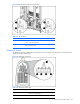
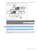
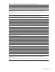
Figure 4-40 Bus Bar LEDs (cables removed for clarity)
Table 4-41 Bus Bar LEDs
Item LED Description Status
1 DC Power Off = No DC power available
Green = DC Power available
2 Polarity Off = Polarity correct
Red = Polarity reversed
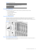
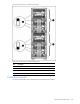
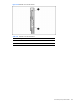
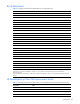
Diagnostic Station
The diagnostic station has multiple LEDs to indicate power and network functions. Use Figure 4-41 and Table 4-42 to
identify LED locations and functions.
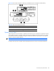
Figure 4-41 Diagnostic station LEDs
Table 4-42 Diagnostic Station LEDs
Item LED Description Status
1 Power and health Green = Power on
Red = Power supply failure
2 NIC link/activity Green = Linked to network