
HP ProLiant BladeSystem p-Class System Maintenance and Service Guide

Connectors, LEDs, and Switches 102
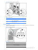
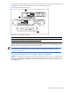
Table 4-42 Diagnostic Station LEDs
Item LED Description Status
3 NIC link/activity
4 NIC link/activity
5 NIC link/activity
Flashing green = Network activity
Off = No activity
Switches and Buttons
Use the following sections to identify the locations and functions of push-button and system switches.
• Power On/Standby Button
• Reset and Unit Identification Buttons
• Dynamic Power Saver
• Power Configuration Switches
• CGESM Switch Modules
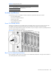
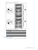
Power On/Standby Button
Setting the server blade Power On/Standby button to the standby position removes power from most areas of the
server blade. This process may take 30 seconds, during which time some internal circuitry remains active.
Use Figure 4-42 to identify the button location. Note that this is only one example. The Power On/Standby button for
other server blade models may look different.
Figure 4-42 Power On/Standby button (BL30p server blades shown)
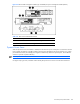
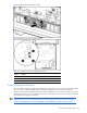
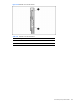
Reset and Unit Identification Buttons
Each management module contains a reset button and unit identification (UID) button. Use Figure 4-43 and Table 4-
43 to identify the button locations and functions.