
HP ProLiant BladeSystem p-Class System Maintenance and Service Guide

Connectors, LEDs, and Switches 104
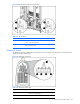
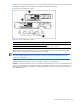
Figure 4-44 Removing the management module
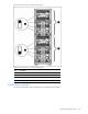
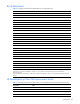
Figure 4-45 Setting Dynamic Power Saver switches
Table 4-44 Dynamic Power Saver Configuration Switches
Position Function
1 Dynamic Power Saver disabled (default)
2 Dynamic Power Saver enabled
3 Reserved (Off=default)
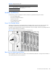
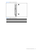
Power Configuration Switches
The server blade management modules and HP BladeSystem p-Class power enclosure power management modules
have a two-position switch that identifies the use of single or multiple power zones in the rack environment.
The zone 1 switch setting is the default position; it is used for scalable bus bar, one set of mini bus bars, and power
bus box solutions. The zone 2 switch setting is only used for a secondary power zone when you configure a full-rack
42U solution with two pairs of mini bus bars.
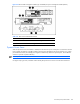
IMPORTANT: In installations configured with the HP BladeSystem p-Class 1U Power Enclosures and Power
Supplies, the power zones are calculated dynamically using the topology information from all the connected
enclosures. Disregard the power zone switch and LEDs on the HP BladeSystem p-Class 1U Power Enclosure.