
HP ProLiant BladeSystem p-Class System Maintenance and Service Guide

Connectors, LEDs, and Switches 105
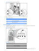
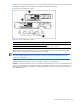
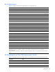
For the system to recognize multiple power zones and rack topology properly, you must set these switches at the time
of installation. Use Figure 4-46 and Table 4-45 to identify switch locations and settings.
Figure 4-46 Power configuration switches
Table 4-45 Power Configuration Switches
Item Description Positions
1 Server blade management module power configuration switch
2 Power management module power configuration switch
Up = Zone 2 (secondary)
Down = Zone 1 (default)
After the initial power-up, use the LEDs to verify correct switch settings. Refer to the “Server Blade Management
Modules” and “Power Management Module” sections in this chapter.
IMPORTANT: All power configuration switches in the same zone must be set to the same position. The system
issues alerts and the management link connector LEDs on the power management modules flash when these
switches are set improperly.
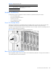
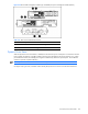
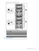
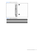
To set the switches for multiple power zones, use Example 1, Figure 4-47, and Table 4-46:
Example1: A full-rack 42U solution with two pairs of mini bus bars requires two power zones. To distinguish the two
power zones, set all the power configuration switches on management modules in the upper zone (zone 2) to the up
position; the power configuration switches on the management modules in the lower zone (zone 1) remain in the
down (default) position.