
HP ProLiant BladeSystem p-Class System Maintenance and Service Guide


Removal and Replacement Procedures 34
1. Remove the interconnect switch. Refer to the “RJ-45 Patch Panels and Interconnect Switches” section in this
chapter.
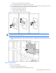
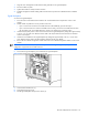
2. Remove the GbE2 Interconnect Switch cover.
Figure 2-5 Removing the GbE2 Interconnect Switch cover
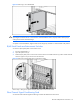
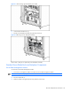
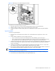
3. Remove the Fibre Channel signal-conditioning card.
Figure 2-6 Removing the Fibre Channel signal-conditioning card
Reverse steps 1 through 3 to replace the Fibre Channel signal-conditioning card.
Patch Panel RJ-45 and Interconnect Modules
Identify the proper number of modules for the interconnect solution:
• Each RJ-45 patch panel has two patch panel RJ-45 modules:
• A 10-connector module (near the top of the communication bay)
• A six-connector module (near the bottom of the communication bay)
• Each GbE Interconnect Switch has one interconnect module with connectors (near the top of the communication
bay).
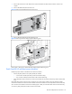
Each GbE2 Interconnect Switch can have a maximum of two interconnect modules if using the optional OctalFC
interconnect module. The connectors for the OctalFC interconnect module are near the top of the communication bay.
The connectors for the Ethernet interconnect module (copper or fiber) are near the bottom of the communication bay.
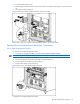
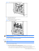
To remove a patch panel RJ-45 module or interconnect module: