
HP ProLiant BladeSystem p-Class System Maintenance and Service Guide


Removal and Replacement Procedures 36
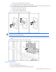
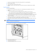
1. Align the server management module with the metal guide tabs on the signal backplane.
2. Press the module into place.
3. Tighten the thumbscrew to fully seat the connectors.
4. Install the management module cabling. Refer to the HP ProLiant p-Class Server Blade Enclosure Installation
Guide.
Signal Backplane
To remove the signal backplane:
1. Power down the server blade enclosure. Refer to the “Server Blade Enclosure Preparation” section in this
chapter.
2. Decide whether to perform this service procedure in the rack:
• If you can access the rear of the server blade enclosure without difficulty, proceed with step 3.
• If you cannot access the rear of the server blade enclosure easily, remove the server blade enclosure from
the rack. Refer to the “Server Blade Enclosure” section in this chapter; then, proceed to step 5.
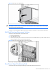
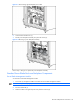
3. Unseat the RJ-45 patch panels or interconnect switches from the signal backplane by sliding them approximately
2.54 cm (1 in) out of the server blade enclosure. Refer to the “RJ-45 Patch Panels and Interconnect Switches”
section in this chapter.
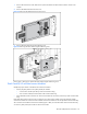
4. Unseat the server blades from the signal backplane by sliding them approximately 2.54 cm (1 in) out of the
server blade enclosure. Refer to the documentation shipped with the server blades.
5. Remove the server blade management module. Refer to the “Server Blade Management Module” section in this
chapter.
IMPORTANT: For ease of removal, it may be necessary to disconnect the grounding cable (facility DC
configuration only) from the server blade enclosure.
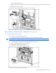
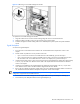
6. Disconnect the signal backplane power cable from the signal backplane.
Figure 2-9 Disconnecting the signal backplane power cable
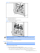
7. Loosen the three thumbscrews (1).
8. Disengage the locking pins (2).
9. Pull the signal backplane away from the chassis (3).