
HP ProLiant BladeSystem p-Class System Maintenance and Service Guide


Removal and Replacement Procedures 40
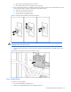
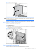
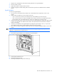
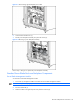
Figure 2-14 Disconnecting signal and power backplane cables
8. Loosen the three thumbscrews (1).
9. Disengage the locking pins (2).
10. Pull the signal backplane away from the chassis (3).
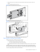
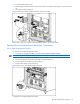
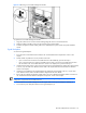
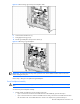
Figure 2-15 Removing a signal backplane
IMPORTANT: The replacement part ships with a protective cover on the VHDM connectors. Remove this cover
before installing the new part.
Reverse steps 1 through 10 to replace the signal backplane.
Power Backplane Assembly
WARNING! To reduce the risk of injury from hot surfaces, allow external components to cool before servicing
them.
To remove the power backplane assembly:
1. Decide whether to perform this service procedure in the rack:
• If you can access the rear of the server blade enclosure without difficulty, proceed with step 3.
• If you cannot access the rear of the server blade enclosure easily, remove the server blade enclosure from
the rack. Refer to the “Server Blade Enclosure” section in this chapter; then, proceed with step 5.