
HP ProLiant BladeSystem p-Class System Maintenance and Service Guide


Removal and Replacement Procedures 42
3. Power down the server blade enclosure. Refer to the “Server Blade Enclosure Preparation” section in this
chapter.
NOTE: If you are only removing the server blade enclosure to service its non-hot-plug components, server blade
blanks can remain installed.
4. Remove both RJ-45 patch panels or interconnect switches. Refer to the “RJ-45 Patch Panels and Interconnect
Switches” section in this chapter.
5. Remove all interconnect modules. Refer to the “Patch Panel RJ-45 and Interconnect Modules” section in this
chapter.
6. Disconnect the grounding cable, if you have a facility DC environment.
7. Disconnect any management module cables from the server blade management module.
WARNING! At least two people must lift a server blade enclosure together when removing it from the rack.
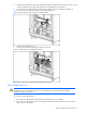
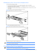
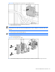
8. Loosen the front panel thumbscrews (1).
9. Slide the enclosure out of the rack (2).
Figure 2-18 Removing a server blade enclosure
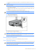
10. Place the enclosure on a sturdy, level surface.
Reverse steps 1 through 10 to replace a server blade enclosure.
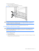
WARNING! At least two people must lift a server blade enclosure into the rack together. If the enclosure is
installed into the rack above chest level, a third person MUST assist with aligning the enclosure with the rails
while the other two people support the weight of the enclosure.
Power Enclosure Components
Use the procedures in this section to service HP BladeSystem p-Class power enclosures.
Power Components Preparation
To service the power enclosure, bus bars, or power bus boxes, you must isolate them from the input power source.
CAUTION: The following procedures remove all power from power distribution devices and the server blades
connected to these devices. To prevent possible data loss, you may choose to power down the server blades
and server blade enclosures before proceeding.