
HP ProLiant BladeSystem p-Class System Maintenance and Service Guide


Removal and Replacement Procedures 46
HP BladeSystem p-Class 1U Power Enclosure Backplane Board
To remove the power backplane assembly:
1. Power down the system. Refer to the “Power Components Preparation” section in this chapter.
2. Remove the power management module. Refer to the “HP BladeSystem p-Class 1U Power Enclosure Power
Management Module” section in this chapter.
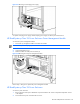
3. Remove the power enclosure from the rack. Refer to the “HP BladeSystem p-Class 1U Power Enclosure” section
in this chapter.
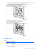
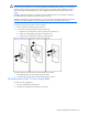
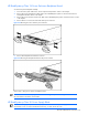
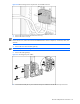
4. Remove the four T-10 screws from the sides of the power enclosure.
Figure 2-24 Removing the screws from the power enclosure
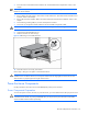
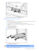
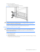
5. Remove the backplane board from the enclosure
Figure 2-25 Removing the backplane board from the power enclosure
Reverse steps 1 through 5 to replace a backplane board.
NOTE: Use a text-based terminal program to connect to the diagnostic port on the management module to set
the serial number to the chassis serial number.
HP BladeSystem p-Class 3U Power Supply Blank
IMPORTANT: In single-phase power enclosures, bays 3 and 6 are not used and power supply blanks are
secured with a screw. To remove the blanks in these bays, you must remove the screw.