
HP ProLiant BladeSystem p-Class System Maintenance and Service Guide


Removal and Replacement Procedures 49
3. If you have bus bars, refer to steps 3 through 6 of the “Scalable or Mini Bus Bars” section in this chapter.
4. If you have power bus boxes, refer to steps 3 through 5 of the “Power Bus Box” section in this chapter.
5. Disconnect the load-balancing signal cable, if you have two power enclosures installed in a scalable bus bar
configuration.
6. Remove the power management module. Refer to the “HP BladeSystem p-Class 3U Power Enclosure Power
Management Module” section in this chapter.
7. Remove all power supply blanks. Refer to the “HP BladeSystem p-Class 3U Power Supply Blank” section in this
chapter.
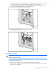
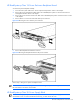
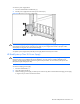
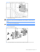
8. Loosen the front panel thumbscrews (1).
9. Slide the power enclosure out of the rack (2).
WARNING! At least two people must lift an enclosure together when removing it from the rack..
Figure 2-29 Removing a 3U power enclosure
Reverse steps 1 through 9 to replace the power enclosure.
Power Distribution Components
Use the procedures in this section to service HP BladeSystem p-Class power distribution components.
NOTE: Power distribution devices (scalable bus bar and mini bus bar) are not required when installing the HP
BladeSystem p-Class 1U Power Enclosure. The power enclosure is designed to connect directly to one server
blade enclosure.
Scalable or Mini Bus Bars
To remove the scalable or mini bus bars:
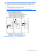
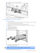
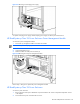
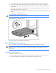
1. Remove power from the bus bars. Refer to the “Power Components Preparation” section in this chapter.
2. Disconnect all bus bar couplers (both A and B sides) from the server blade enclosures.