
HP ProLiant BladeSystem p-Class System Maintenance and Service Guide


Removal and Replacement Procedures 50
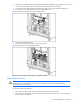
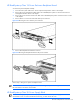
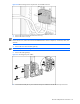
Figure 2-30 Disconnecting bus bar couplers from server blade enclosures
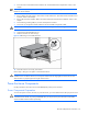
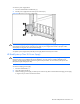
3. Remove the screws from the bus bar access cover (1).
4. Remove the access cover (2).
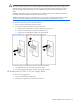
NOTE: The access covers for mini bus bars are different from scalable bus bars. For an illustration of the mini
bus bar access cover, refer to the “Mini and Scalable Bus Bars” section in Chapter 4, “Connectors, LEDs, and
Switches.”
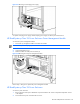
5. Remove the screw from the cable guide (3).
NOTE: You may need to use a magnetized screwdriver to reinstall this screw.
6. Remove the cable guide (4).
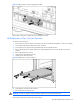
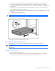
Figure 2-31 Accessing the power cables
7. Disconnect the facility DC or power enclosure DC power cables from the bus bar DC input connectors.