
HP ProLiant BladeSystem p-Class System Maintenance and Service Guide

Connectors, LEDs, and Switches 71
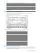
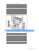
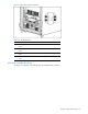
Table 4-1 Enclosure, Management Module, and Backplane Components
Item Description
14 Load-balancing signal cable connector
15 Power enclosure
16 DC power input connector for bus B
17 Server blade management module iLO port
* The service port enables qualified service personnel to run infrastructure diagnostics. Refer to Chapter 3, “Diagnostic Tools,”
for more information.
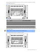
HP BladeSystem p—Class 1U Power Enclosures
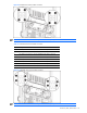
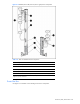
Use Figure 4-3 and Table 4-2 to identify the HP BladeSystem p-Class 1U Power Enclosure components.
Figure 4-3 HP BladeSystem p-Class 1U Power Enclosure
Table 4-2 Enclosure, Management Module, and Backplane Components
Item Description
1 DC output power connector for bus B
2 AC input power connector for bay 6
3 AC input power connector for bay 5
4 AC input power connector for bay 4
5 Power enclosure management link connector (to enclosure below, if necessary)
6 Power management module service port
7 Power enclosure management link connector (to enclosure above)
8 AC input power connector for bay 3
9 AC input power connector for bay 2
10 AC input power connector for bay 1
11 DC output power connector for bus A
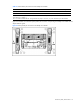
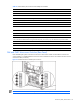
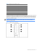
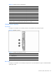
RJ-45 Patch Panel and RJ-45 Patch Panel 2
A pair of interconnects (either patch panels or interconnect switches) provide all network data connections for one
server blade enclosure. Each RJ-45 Patch Panel and RJ-45 Patch Panel 2 has two RJ-45 interconnect modules: a
10-connector module and a 6-connector module.