
HP ProLiant BladeSystem p-Class System Maintenance and Service Guide

Connectors, LEDs, and Switches 81
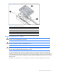
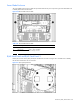
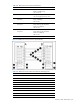
Figure 4-15 Power bus box components (some internal pieces removed for clarity)
Table 4-14 Power Bus Box Components
Item Description
1 DC power input connectors
2 Access cover
3 DC power output cables with coupler (installed)
Circuit breaker (on opposite side)
Diagnostic and Local I/O Cables
CAUTION: Disconnect the diagnostic cable or the local I/O cable from the port when not in use. The port and
connector do not provide permanent connections.
CAUTION: Rear iLO connector performance degrades when the local I/O cable or the diagnostic cable is in
use, even when the iLO connector on the cable is not in use.
CAUTION: Always match the server blade connector on the local I/O cable to the I/O port that is located next
to the I/O icon. Match the server blade connector on the diagnostic cable to the diagnostic port on the front of
the server blade. Mismatched cables prevent proper connection.
Use either the diagnostic cable or the local I/O cable to perform some server blade configuration and diagnostic
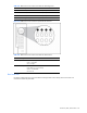
procedures. Depending on the model, the server blade will have either a diagnostic port or an I/O port. The I/O port
only accepts the local I/O cable and the diagnostic port only accepts the diagnostic cable. If the server blade has an
I/O icon next to the I/O port on the front of the server blade, use the local I/O cable. If the port has no icon, use the
diagnostic cable.
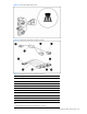
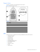
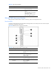
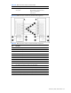
Use Figure 4-16 to identify the I/O icon. Use Figure 4-17 and Table 4-15 to identify diagnostic cable connectors.