
HP ProLiant BladeSystem p-Class System Maintenance and Service Guide

Connectors, LEDs, and Switches 83
Diagnostic Station
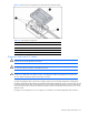
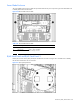
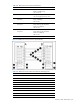
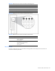
Use Figure 4-18 and Table 4-16 to identify diagnostic station connectors.
Figure 4-18 Diagnostic station connectors
Table 4-16 Diagnostic Station Connectors
Item Description
1 Data transfer port
2 DC power connectors
3 RJ-45 connector for NIC
4 RJ-45 connector for NIC
5 RJ-45 connector for NIC
6 RJ-45 connector for NIC
7 Reserved
8 AC power connector
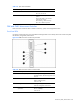
LEDs
Use the following section to identify LEDs on the following HP BladeSystem p-Class system components:
• Hot-plug SCSI hard drives
• Server blade enclosure
• RJ-45 patch panels
• Interconnect switches
• Interconnect modules
• Server blade management module
• Power management module
• Power enclosure
• Hot-plug power supply
• Bus bars
• Diagnostic station