
HP ProLiant BladeSystem p-Class System Maintenance and Service Guide

Connectors, LEDs, and Switches 89
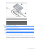
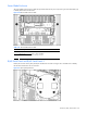
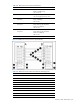
Table 4-23 GbE2 Interconnect Switch Front Panel LEDs
Item LED Description Status
2 Power status LED Green = Power on
Amber = Stand-by mode
Off = Power off
3 Management status LED Flashing = Management session active
Off = No management session active
4 Front panel RJ-45 connector link
speed LEDs
Amber = 1000 Mbps
Green = 100 Mbps
Off = No link
5 Front panel RJ-45 connector link
activity LEDs
Green = Link and no activity
Green flashing = Link and activity
Amber = Port disabled
Off = No link
6 Front panel RJ-45 connector link
activity LEDs
Green = Link and no activity
Green flashing = Link and activity
Amber = Port disabled
Off = No link
7 10G LED Reserved for future use
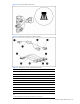
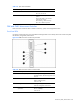
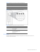
Figure 4-26 GbE2 Interconnect switch front panel NIC LED
Table 4-24 GbE2 Interconnect Switch Front Panel NIC LED Assignments
Item Description
1 Server blade bays 1 and 9* NICs
2 Server blade bays 2 and 10* NICs
3 Server blade bays 3 and 11* NICs
4 Server blade bays 4 and 12* NICs
5 Server blade bays 5 and 13* NICs
6 Server blade bays 6 and 14* NICs
7 Server blade bays 7 and 15* NICs
8 Server blade bays 8 and 16* NICs
9 Ports 17 and 18 inter-switch crosslinks
10 Port 19 RJ-45 connector for switch A rear panel uplink