
HP ProLiant BladeSystem p-Class System Maintenance and Service Guide

Connectors, LEDs, and Switches 90
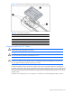
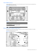
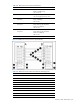
Table 4-24 GbE2 Interconnect Switch Front Panel NIC LED Assignments
Item Description
11 Port 20 RJ-45 connector for switch A rear panel uplink
12 Port 21 RJ-45 connector for switch A rear panel uplink
13 Port 22 RJ-45 connector for switch A rear panel uplink
* Server bays 9 through 16 apply only when using BL30p series server blades
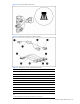
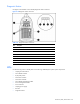
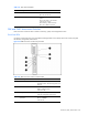
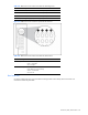
Figure 4-27 GbE2 Interconnect Switch front panel NIC LED functions
Table 4-25 GbE2 Interconnect Switch Front Panel NIC LED Functions
Item LED Description Status
1 Link speed Amber = 1000 Mbps
Green = 100 Mbps
Off = 10 Mbps
2 Link activity Green = Link and no activity
Green flashing = Link and activity
Amber = Port disabled
Off = No link
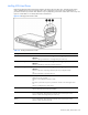
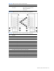
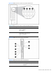
Rear Panel LEDs
Use Figure 4-28 through Figure 4-32 and Table 4-26 through Table 4-30 to identify interconnect switch and
interconnect module rear panel LEDs.