
HP ProLiant BladeSystem p-Class System Maintenance and Service Guide

Connectors, LEDs, and Switches 94
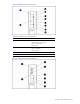
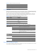
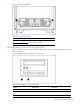
Table 4-30 OctalFC Interconnect Module LEDs
Item LED Description Status
4 Fibre Channel ports 4 and 12* Green = Link
Off = No link
5 Fibre Channel ports 5 and 13* Green = Link
Off = No link
6 Fibre Channel ports 6 and 14* Green = Link
Off = No link
7 Fibre Channel ports 7 and 15* Green = Link
Off = No link
7 Fibre Channel ports 8 and 16* Green = Link
Off = No link
* Server bays 9 through 16 apply only when using BL30p series server blades.
CGESM Switch Modules
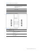
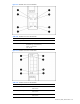
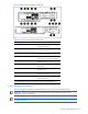
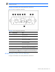
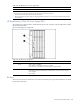
Use Figure 4-33 and Table 4-31 through Table 4-34 to identify LED locations and functions on the CGESM switch
module:
Figure 4-33 CGESM switch module LEDs
Table 4-31 CGESM switch module LEDs
Item Description
1 System (Syst) LED
2 Mode LEDs
3 Downlink ports 1-16 LEDs
4 Cross-connect (XC) ports 17 and 18 LEDs
5 Uplink ports 19-22 LEDs
6 Front panel (FP) Ethernet ports 23 and 24 LEDs
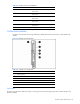
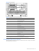
System LED
The System (Sys) LED shows whether the system is receiving power and is functioning properly. Table 4-32 lists the LED colors
and their meanings.