
HP ProLiant BladeSystem p-Class System Maintenance and Service Guide

Connectors, LEDs, and Switches 96
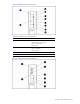
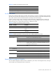
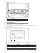
Figure 4-34 Server blade management module LEDs
Table 4-35 Server Blade Management Module LEDs
Item LED Description Status
1 Fault Red = Fault condition
Off = No fault condition
2 Unit identification Blue = Unit identified
Off = Unit not identified
3 Power Green = Power available
Off = No power available
4 Power configuration Off/Green = Power zone 1 (default)
Green/Green = Power zone 2 (secondary)
5 Management bus activity Amber = Activity *
Off = No activity
6 Management link Green = Link *
Off = No link
7 iLO Activity Green = Activity
Off = No Activity
8 iLO Link Green = Network Link
Off = No Network Link
9 iLO Link Green = Network Link
Off = No Network Link
* All management link connector LEDs flash on the server blade management modules and
power management modules when management modules are cabled improperly.
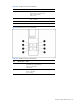
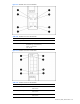
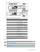
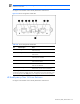
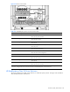
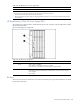
Power Management Module
The power management module has LEDs for identification, power status, and management activity.
IMPORTANT: All power management module management link connector LEDs flash when the power
configuration switch is set improperly
IMPORTANT: If management modules are cabled improperly, all management link connector LEDs flash on all
management modules.