
HP ProLiant BladeSystem p-Class System Maintenance and Service Guide

Connectors, LEDs, and Switches 98
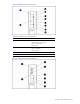
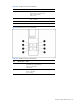
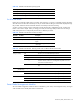
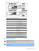
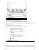
Figure 4-36 Power enclosure LEDs
Table 4-37 HP BladeSystem p-Class 1U Power Enclosure LEDs
Item LED Description Status
1 Bus B DC power LED Green = DC power available
Off = No DC power available
2 Management link activity LED Amber flashing = Network activity
Off = No link or activity
3 Management link LED Green = Network linked
Off = No link
4 Power LED Green = Management module is powered up
Off = No power
5 Fault status LED Red flashing = Fault process activity
Off = No fault process activity
6 UID LED Blue = Identified
Off = No active remote management
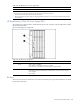
7,8 Power zone LEDs See note
1
9 Management link activity LED Amber flashing = Network activity
Off = No link or activity
10 Management link LED Green = Network linked
Off = No link
11 Bus A DC power LED Green = DC power available
Off = No DC power available
1
Power zones are automatically configured based on the location of the enclosures in the rack and the management link
connections. Disregard the power zone switch and LEDs on the HP BladeSystem 1U Power Enclosure.
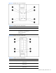
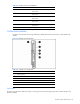
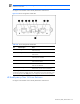
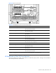
HP BladeSystem p-Class 3U Power Enclosure
The power enclosure has two LEDs, one for each bus, to indicate DC power presence. Use Figure 4-37 and Table 4-
38 to identify LED locations and functions.