HP ProLiant BL25p Server Blade Maintenance and Service Guide December 2005 (Fourth Edition) Part Number 377851-004A
© Copyright 2005 Hewlett-Packard Development Company, L.P. The information contained herein is subject to change without notice. The only warranties for HP products and services are set forth in the express warranty statements accompanying such products and services. Nothing herein should be construed as constituting an additional warranty. HP shall not be liable for technical or editorial errors or omissions contained herein. Microsoft and Windows are U.S. registered trademarks of Microsoft Corporation.
Contents Illustrated parts catalog ................................................................................................................. 5 Customer self repair................................................................................................................................... 5 Server blade components ........................................................................................................................... 6 Removal and replacement procedures .....................
Index.........................................................................................................................................
Illustrated parts catalog In this section Customer self repair ................................................................................................................................. 5 Server blade components .......................................................................................................................... 6 Customer self repair What is customer self repair? HP's customer self-repair program offers you the fastest service under either warranty or contract.
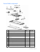
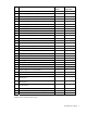
Server blade components Item Description Spare part number Customer replaceable? Mechanical components 1 Access panel 371709-001 Yes 2 Hard drive blank 122759-001 Yes Boards 3 Power button/LED board kit with LED cable (cable not shown *) 371706-001 Yes 4 SCSI backplane with cables (cables not shown *) 371701-001 Yes 5 System board 381811-001 Yes 6 Standard NIC mezzanine card 381816-001 Yes 7 HP Smart Array 6i Controller 371702-001 Yes 381812-001 Yes 381836-001 Yes System
Description Spare part number Customer replaceable? b) 2.6-GHz, single-core AMD Opteron™ Model 252 * 381837-001 Yes c) 2.8-GHz, single-core AMD Opteron™ Model 254 * 404041-001 Yes d) 1.8-GHz, dual-core AMD Opteron™ Model 265 * 391837-001 Yes e) 2.0-GHz, dual-core AMD Opteron™ Model 270 * 391838-002 Yes f) 2.2-GHz, dual-core AMD Opteron™ Model 275 * 391837-003 Yes g) 2.
Removal and replacement procedures In this section Safety considerations................................................................................................................................ 8 Server blade preparation ........................................................................................................................ 11 Access panel .........................................................................................................................................
Server blade warnings and cautions WARNING: To reduce the risk of injury from high-current electrical energy, do not remove the server blade access panel when power is applied through the HP ProLiant p-Class diagnostic station. Remove all power from the server blade before removing the access panel. WARNING: To reduce the risk of shock or injury from high-current electrical energy, do not remove the server blade access panel while the server blade is installed in the server blade enclosure.
WARNING: To reduce the risk of personal injury from hot surfaces, allow the drives and the internal system components to cool before touching them. CAUTION: Protect the server from power fluctuations and temporary interruptions with a regulating uninterruptible power supply (UPS). This device protects the hardware from damage caused by power surges and voltage spikes and keeps the system in operation during a power failure.
Server blade preparation To service any internal server blade component, power down the server blade and remove it from the server blade enclosure. CAUTION: Electrostatic discharge (ESD) can damage electronic components. Be sure that you are properly grounded (earthed) before beginning any installation procedure. System power in server blades does not completely shut off with the front panel power switch or iLO Virtual Power Button feature.
Access panel To remove the component: 1. Power down the server blade and remove it from the server blade enclosure ("Server blade preparation" on page 11). 2. Loosen the thumbscrew. 3. Press down on the thumb indentations, slide the access panel toward the rear of the unit about 1.25 cm (0.5 in), and lift to remove the panel. To replace the component, reverse the removal procedure.
2. Install the hard drive. 3. Determine the status of the hard drive from the hot-plug hard drive LEDs ("Hot-plug SCSI hard drive LEDs" on page 37). Resume normal server operations. To remove the component, reverse the installation procedure. DIMMs To remove the component: 1. Power down the server blade and remove it from the server blade enclosure ("Server blade preparation" on page 11). 2. Remove the access panel ("Access panel" on page 12). 3. Open the DIMM slot latches. 4.
• Both DIMM slots in a memory bank must be populated. • Both DIMMs in a memory bank must be identical. • Processor 1 memory bank 1 must always be populated. • If mixing dual- and single-rank DIMMs, the dual-rank DIMMs must be installed in memory bank 1. For optimal performance in most applications, populate memory bank 1 for every populated processor socket. PC3200 DIMMs can either be single- or dual-rank.
3. Open the processor cage latch. 4. Open the processor cage. 5. Remove the heatsink. 6. Open the processor locking lever. 7. Remove the processor. CAUTION: The heatsink is not reusable and must be discarded if removed from the processor after application. CAUTION: Always install a processor or a processor blank and 1P enabler board in processor socket 2. If processor socket 2 is empty, the server blade will not boot. To install the component: 1. Install the processor.
3. Remove the protective cover from the thermal interface. CAUTION: After the cover is removed, do not touch the thermal interface media. IMPORTANT: The heatsink is not reusable and must be discarded if removed from the processor after application. 4. Insert the heatsink and close the processor cage. Closing the processor cage aligns the heatsink. 5. Close and secure the processor cage latch.
CAUTION: To avoid overheating of the dual core processor, the old air baffle must be replaced when upgrading from a single core processor to a dual core processor. IMPORTANT: To ensure proper cooling, be sure the correct processor air baffle (on page 18) is installed at all times. HP Smart Array 6i Controller To remove the component: 1. Power down the server blade and remove it from the server blade enclosure ("Server blade preparation" on page 11). 2.
HP Smart Array 6i battery-backed write cache enabler (optional) To remove the component: 1. Power down the server blade and remove it from the server blade enclosure ("Server blade preparation" on page 11). 2. Remove the access panel ("Access panel" on page 12). CAUTION: Disconnecting the battery module cable will cause any unsaved data in the memory module to be lost. 3. Remove the BBWCE from the controller. 4. Remove the battery from the BBWC memory module.
3. Remove the air baffle. To replace the component, reverse the removal procedure. CAUTION: To avoid overheating of the dual core processor, the old air baffle must be replaced when upgrading from a single core processor to a dual core processor. IMPORTANT: To ensure proper cooling, be sure the correct processor air baffle (on page 18) is installed at all times. Fan assembly To remove the component: 1.
5. Press the fan retention tab and lift the assembly away from the system board. To replace the component, reverse the removal procedure. IMPORTANT: To ensure proper cooling, be sure the correct processor air baffle (on page 18) is installed at all times. Fibre Channel mezzanine (optional) An optional FC mezzanine enables FC support (for clustering capabilities) and SAN connection when used in conjunction with the RJ-45 Patch Panel 2 or the GbE2 Interconnect Switch with FC pass-through option.
IMPORTANT: Refer to the label on the FC mezzanine to verify compatibility with the server blade. Standard NIC mezzanine card To remove the component: 1. Power down the server blade and remove it from the server blade enclosure ("Server blade preparation" on page 11). 2. Remove the access panel ("Access panel" on page 12). 3. Remove the FC mezzanine ("Fibre Channel mezzanine (optional)" on page 20). 4. Loosen the thumbscrews. 5. Lift the standard NIC mezzanine card away from the system board.
SCSI backplane To remove the component: 1. Power down the server blade and remove it from the server blade enclosure. ("Server blade preparation" on page 11) 2. Remove the access panel ("Access panel" on page 12). 3. Remove any hot-plug SCSI hard drives or hard drive blanks ("Hard drives" on page 12). 4. Remove the fan assembly ("Fan assembly" on page 19). 5. Disconnect the SCSI backplane power cable from the system board. 6. Remove the plastic air baffle. 7.
Power converter module To remove the component: 1. Power down the server blade and remove it from the server blade enclosure ("Server blade preparation" on page 11). 2. Remove the access panel ("Access panel" on page 12). 3. Loosen the thumbscrew and remove the power converter module. 4. Remove the power converter module retainers from the power converter module and store for use on the new power converter module.
4. Release the latches and lift the DC filter module away from the system board while pushing the power connector into the chassis. To replace the component, reverse the removal procedure. Power button/LED board To remove the component: 1. Power down the server blade and remove it from the server blade enclosure ("Server blade preparation" on page 11). 2. Remove the access panel ("Access panel" on page 12). 3. Remove any hot-plug SCSI hard drives or hard drive blanks ("Hard drives" on page 12). 4.
8. Slide the power button/LED board out of the front of the chassis. IMPORTANT: Be sure the tab at the end of the power button/LED cable is inserted under the power button/LED board bezel. To replace the component, reverse the removal procedure. System board battery If the server blade no longer automatically displays the correct date and time, you may need to replace the battery that provides power to the real-time clock. Under normal use, battery life is 5 to 10 years.
4. Remove the existing battery by pushing the tab aside and pulling the battery straight up. To install the system board battery, push it into the socket until the tab locks in place. System board To remove the component: 1. Power down the server blade and remove it from the server blade enclosure ("Server blade preparation" on page 11). 2. Remove the access panel ("Access panel" on page 12). 3. Remove the DIMMs ("DIMMs" on page 13). 4. Remove the processor and heatsinks ("Processor" on page 14).
13. Disconnect the LED cable from the system board before removing the system board from the server blade. 14. Slide the system board toward the front of the server blade. 15. Lift the system board until it comes off the alignment keys. 16. Lift the edge of the system board nearest the system switches. The edge of the system board nearest the array controller connectors tilts down into the chassis, and the edge of the system board nearest the system switches tilts up out of the chassis. 17.
Server blade bay blank Remove the server blade blank from the server blade enclosure. CAUTION: To prevent improper cooling and thermal damage, do not operate the server blade enclosure unless all bays are populated with either a component or a blank. To replace a server blade blank, align the blank with the empty bay and slide it in until the blank is fully seated.
Diagnostic tools In this section HP Insight Diagnostics............................................................................................................................. 29 Survey Utility.......................................................................................................................................... 29 Integrated Management Log ....................................................................................................................
• For Linux: IML Viewer Application • From within the iLO user interface • From within HP Insight Diagnostics (on page 29) For more information, refer to the Management CD in the HP ProLiant Essentials Foundation Pack.
Server component identification In this section Front panel components .......................................................................................................................... 31 Front panel LEDs .................................................................................................................................... 32 Rear panel components...........................................................................................................................
Front panel LEDs Item Description Status 1 UID LED Blue = Identified Blue flashing = Active remote management Off = No active remote management 2 Health LED Green = Normal Flashing = Booting Amber = Degraded condition Red = Critical condition 3 NIC 1 LED* Green = Network linked Green flashing = Network activity Off = No link or activity 4 NIC 2 LED* Green = Network linked Green flashing = Network activity Off = No link or activity 5 NIC 3 LED* Green = Network linked Green flashing = Networ
Item Description Status 10 Fault status Flashing = Fault process activity Off = No fault process activity * Actual NIC numeration depends on several factors, including the operating system installed on the server blade.
Internal components Item Description 1 System maintenance switch (SW1) 2 DC filter module 3 Standard NIC mezzanine card 4 System battery 5 Processor 2 memory bank 2 6 Processor 2 memory bank 1 (shown populated) 7 DIMMs 5-8 8 Processor socket 2 (shown populated) 9 SCSI backplane board connector 2 10 Fan connectors 11 Power button/LED board connector 12 SCSI backplane board connector 1 13 Processor socket 1 (shown populated) 14 DIMMs 1-4 15 Processor 1 memory bank 1(shown popul
Item Description 18 HP Smart Array 6i Controller 19 Power converter modules 20 FC mezzanine (optional) System maintenance switch Position Function Default 1* iLO Security override Off 2 Configuration lock Off 3 Reserved Off 4 Reserved Off 5* Password disabled Off 6* Reset configuration Off 7 Reserved Off 8 Reserved Off *To access redundant ROM, set S1, S5, and S6 to ON.
IMPORTANT: When the server blade boots after NVRAM is cleared, a delay of up to 2 minutes is normal. During this delay, the system appears non-functional. Do not attempt any procedures during the delay. Accessing the redundant ROM If the system ROM is corrupted, you can set the system to use the backup version or redundant ROM. To use the redundant ROM: 1. Power down the server blade and disconnect the server blade from all power sources ("Server blade preparation" on page 11). 2.
Item Connector Description 6 iLO RJ-45 (10/100 Ethernet) For connecting an Ethernet to the server blade iLO interface from a client device Hot-plug SCSI hard drive LEDs Item LED description Status 1 Activity status On = Drive activity Flashing = High activity on the drive or drive is being configured as part of an array. Off = No drive activity 2 On = Drive is part of an array and is currently working. Online status Flashing = Drive is actively online. Off = Drive is offline.
Activity LED (1) Online LED Fault LED (2) (3) Interpretation On or flashing Flashing Do not remove the drive. Removing a drive may terminate the current operation and cause data loss. Off The drive is rebuilding or undergoing capacity expansion. On Off Off Do not remove the drive. The drive is being accessed, but (1) it is not configured as part of an array; (2) it is a replacement drive and rebuild has not yet started; or (3) it is spinning up during the POST sequence.
Specifications In this section Environmental specifications .................................................................................................................... 39 Server specifications ...............................................................................................................................
Acronyms and abbreviations BBWC battery-backed write cache BIOS Basic Input/Output System DDR double data rate ESD electrostatic discharge FC Fibre Channel I/O input/output iLO Integrated Lights-Out IML Integrated Management Log IP Internet Protocol LED light-emitting diode NIC network interface controller POST Power-On Self Test Acronyms and abbreviations 40
PSP ProLiant Support Pack RBSU ROM-Based Setup Utility RILOE Remote Insight Lights-Out Edition ROM read-only memory SA Smart Array SCSI small computer system interface SIM Systems Insight Manager UID unit identification UPS uninterruptible power system USB universal serial bus Acronyms and abbreviations 41
Index A access panel 12 air baffle 18, 19, 22 array controllers 34 B batteries, care and storage 25 battery-backed write cache 34 battery-backed write cache battery pack 34 battery-backed write cache enabler 17, 18, 34 buttons 31 C cable connector identification 36 cables 36 cabling 36 cautions 9 component identification 31, 32, 33, 35 components 31 connectors 31, 36 CSR (customer self repair) 5 customer self repair 5 D DC filter module 23, 34 diagnostic tools 29 diagnostics utility 29 DIMM installation
P power button 31, 34 power button/LED board 24 power converter module 23, 34 PPM failure LEDs 37 preparation procedures 11 processors 14, 34 R rack warnings 9 redundant ROM 36 removal and replacement procedures 8 S safety considerations 8 SCSI backplane 22 serial port 36 server blade bay blank 28 server, rear panel components 33 Smart Array 6i Controller 17 specifications 39 specifications, server 39 Standby mode 11 static electricity 8 Survey Utility 29 symbols on equipment 10 system battery 25, 34 syst