HP ProLiant BL260c Generation 5 Server Blade Maintenance and Service Guide Part Number 459408-003 September 2008 (Third Edition)
© Copyright 2008 Hewlett-Packard Development Company, L.P. The information contained herein is subject to change without notice. The only warranties for HP products and services are set forth in the express warranty statements accompanying such products and services. Nothing herein should be construed as constituting an additional warranty. HP shall not be liable for technical or editorial errors or omissions contained herein. Microsoft, and Windows are U.S. registered trademarks of Microsoft Corporation.
Contents Customer self repair ...................................................................................................................... 5 Parts only warranty service ......................................................................................................................... 5 Illustrated parts catalog ............................................................................................................... 16 Server blade components ..........................................
System board components........................................................................................................................ 55 System maintenance switch............................................................................................................. 55 HP c-Class Blade SUV Cable..................................................................................................................... 56 Specifications ................................................................
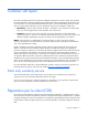
Customer self repair HP products are designed with many Customer Self Repair (CSR) parts to minimize repair time and allow for greater flexibility in performing defective parts replacement. If during the diagnosis period HP (or HP service providers or service partners) identifies that the repair can be accomplished by the use of a CSR part, HP will ship that part directly to you for replacement. There are two categories of CSR parts: • Mandatory—Parts for which customer self repair is mandatory.
• Obligatoire - Pièces pour lesquelles la réparation par le client est obligatoire. Si vous demandez à HP de remplacer ces pièces, les coûts de déplacement et main d'œuvre du service vous seront facturés. • Facultatif - Pièces pour lesquelles la réparation par le client est facultative. Ces pièces sont également conçues pour permettre au client d'effectuer lui-même la réparation.
NOTA: alcuni componenti HP non sono progettati per la riparazione da parte del cliente. Per rispettare la garanzia, HP richiede che queste parti siano sostituite da un centro di assistenza autorizzato. Tali parti sono identificate da un "No" nel Catalogo illustrato dei componenti. In base alla disponibilità e alla località geografica, le parti CSR vengono spedite con consegna entro il giorno lavorativo seguente.
anrufen und sich von einem Mitarbeiter per Telefon helfen lassen. Den Materialien, die mit einem CSRErsatzteil geliefert werden, können Sie entnehmen, ob das defekte Teil an HP zurückgeschickt werden muss. Wenn es erforderlich ist, das defekte Teil an HP zurückzuschicken, müssen Sie dies innerhalb eines vorgegebenen Zeitraums tun, in der Regel innerhalb von fünf (5) Geschäftstagen.
Centro de asistencia técnica de HP y recibirá ayuda telefónica por parte de un técnico. Con el envío de materiales para la sustitución de componentes CSR, HP especificará si los componentes defectuosos deberán devolverse a HP. En aquellos casos en los que sea necesario devolver algún componente a HP, deberá hacerlo en el periodo de tiempo especificado, normalmente cinco días laborables. Los componentes defectuosos deberán devolverse con toda la documentación relacionada y con el embalaje de envío.
periode, gewoonlijk vijf (5) werkdagen, retourneren aan HP. Het defecte onderdeel moet met de bijbehorende documentatie worden geretourneerd in het meegeleverde verpakkingsmateriaal. Als u het defecte onderdeel niet terugzendt, kan HP u voor het vervangende onderdeel kosten in rekening brengen. Bij reparatie door de klant betaalt HP alle verzendkosten voor het vervangende en geretourneerde onderdeel en kiest HP zelf welke koerier/transportonderneming hiervoor wordt gebruikt.
Serviço de garantia apenas para peças A garantia limitada da HP pode incluir um serviço de garantia apenas para peças. Segundo os termos do serviço de garantia apenas para peças, a HP fornece as peças de reposição sem cobrar nenhuma taxa. No caso desse serviço, a substituição de peças CSR é obrigatória. Se desejar que a HP substitua essas peças, serão cobradas as despesas de transporte e mão-de-obra do serviço.
Customer self repair 12
Customer self repair 13
Customer self repair 14
Customer self repair 15
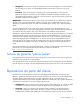
Illustrated parts catalog Server blade components Item Description Spare part number Customer self repair (on page 5) Mechanical components 1 Access panel 468918-001 Mandatory1 2 Hardware and plastics kit 468917-001 Mandatory1 a) Heatsink blank — — b) Air baffle — — c) Enclosure connector cover* — — d) Battery tray* — — e) Server blade handle* — — f) Server blade handle screw* — — g) Server blade handle spring* — — Illustrated parts catalog 16
Item 3 Description Spare part number Customer self repair (on page 5) h) Release button* — — Hard drive cage/bezel assembly 483013-001 Mandatory1 Processors — — a) 1.86-GHz Intel® DT Celeron® processor 445, single-core, uni-processor, 512-MB L2 cache, 1066-MHz FSB** 469660-001 Optional2 b) 2.50-GHz Intel® Xeon® processor X3323, quad-core, uni-processor, 1×6-MB L2 cache, 1333-MHz FSB* ** 469657-001 Optional2 c) 2.
Item Description Spare part number Customer self repair (on page 5) p) 1.86-GHz Intel® Core™ 2 Duo processor 469659-001 E6305, quad-core, uni-processor, 2-MB L2 cache, 1066-MHz FSB* ** Optional2 q) 2.13-GHz Intel® Core™ 2 Duo processor E6405, dual-core, uni-processor, 2-MB L2 cache, 1066-MHz FSB* ** 469658-001 Optional2 r) 2.
Item Description Spare part number Customer self repair (on page 5) i) HP NC512m Dual Port 10GbE Multifunction BL- 448515-001 c Adapter Mandatory1 j) HP NC382m Dual Port 10GbE Multifunction BL- 462748-001 c Adapter Mandatory1 Cables 11 HP c-Class Blade SUV Cable* 416003-001 Mandatory1 12 Hard drive cable* 483014-001 Mandatory1 *Not shown **Do not mix processors with different speeds or cache sizes. 1 Mandatory—Parts for which customer self repair is mandatory.
HP realice su sustitución, puede o no conllevar costes adicionales, dependiendo del tipo de servicio de garantía correspondiente al producto. 3 No: No—Algunos componentes no están diseñados para que puedan ser reparados por el usuario. Para que el usuario haga valer su garantía, HP pone como condición que un proveedor de servicios autorizado realice la sustitución de estos componentes. Dichos componentes se identifican con la palabra “No” en el catálogo ilustrado de componentes.
Removal and replacement procedures Required tools You need the following items for some procedures: • T-15 Torx screwdriver (provided inside the access panel) • Flathead screwdriver • HP Insight Diagnostics software ("HP Insight Diagnostics" on page 50) Safety considerations Before performing service procedures, review all the safety information.
CAUTION: When performing non-hot-plug operations, you must power down the server blade and/or the system. However, it may be necessary to leave the server blade powered up when performing other operations, such as hot-plug installations or troubleshooting. Symbols on equipment The following symbols may be placed on equipment to indicate the presence of potentially hazardous conditions. This symbol indicates the presence of hazardous energy circuits or electric shock hazards.
Power down the server blade Before powering down the server blade for any upgrade or maintenance procedures, perform a backup of critical server data and programs. Depending on the Onboard Administrator configuration, use one of the following methods to power down the server blade: • Use a virtual power button selection through iLO 2. This method initiates a controlled remote shutdown of applications and the OS before the server blade enters standby mode. • Press and release the Power On/Standby button.
4. Place the server blade on a flat, level work surface. Access panel To remove the component: 1. Power down the server blade (on page 23). 2. Remove the server blade (on page 23). 3. Press the access panel release button. 4. Slide the access panel towards the rear of the server blade, and then lift to remove the panel. To replace the component: 1. Place the access panel on top of the server blade. 2. Slide the access panel forward until it clicks into place. DIMMs To remove the component: 1.
3. Remove the access panel ("Access panel" on page 24). 4. Remove the air baffle. To replace the component, reverse the removal procedure. Mezzanine card To remove the component: 1. Power down the server blade (on page 23). 2. Remove the server blade (on page 23). 3. Remove the access panel ("Access panel" on page 24). 4. Remove the mezzanine card. To replace the component, reverse the removal procedure.
Battery tray This component is available for use with future options. To remove the component: 1. Power down the server blade (on page 23). 2. Remove the server blade (on page 23). 3. Remove the access panel ("Access panel" on page 24). 4. Remove the battery tray. To replace the component, reverse the removal procedure. System battery If the server blade no longer automatically displays the correct date and time, you may need to replace the battery that provides power to the real-time clock.
5. Remove the battery. IMPORTANT: Replacing the system board battery resets the system ROM to its default configuration. After replacing the battery, reconfigure the system through RBSU. To replace the component, reverse the removal procedure. Hard drive cage/bezel assembly To remove the component: WARNING: To reduce the risk of personal injury from hot surfaces, allow the drives and the internal system components to cool before touching them. 1. Power down the server blade (on page 23). 2.
4. Disconnect the power and data cable from the system board. 5. Remove the hard drive cage/bezel assembly. To replace the component, reverse the removal procedure. Hard drive To remove the component: 1. Back up all server data on the hard drive. 2. Power down the server blade (on page 23). 3. Remove the server blade (on page 23). 4. Remove the access panel ("Access panel" on page 24).
5. Disconnect the power and data cable from the system board. 6. Remove the hard drive cage/bezel assembly ("Hard drive cage/bezel assembly" on page 27). 7. Remove the four T-15 hard drive screws.
8. Open the hard drive cage and disconnect the cable from the hard drive. 9. Remove the hard drive. To replace the component, reverse the removal procedure. Heatsink blank WARNING: To reduce the risk of personal injury from hot surfaces, allow the drives and the internal system components to cool before touching them. CAUTION: To prevent possible server blade overheating, always populate processor socket 2 with a processor and a heatsink or a processor socket cover and a heatsink blank.
2. Remove the server blade (on page 23). 3. Remove the access panel ("Access panel" on page 24). 4. Remove the hard drive cage/bezel assembly ("Hard drive cage/bezel assembly" on page 27). 5. Remove the heatsink blank. Retain the heatsink blank for future use. To replace the component, reverse the removal procedure. Heatsink WARNING: To reduce the risk of personal injury from hot surfaces, allow the drives and the internal system components to cool before touching them. To remove the component: 1.
5. Remove the heatsink. To replace the component: 1. Clean the old thermal grease from the processor with the alcohol swab. Allow the alcohol to evaporate before continuing. 2. Remove the thermal interface protective cover from the heatsink. CAUTION: Heatsink retaining screws should be tightened in diagonally opposite pairs (in an "X" pattern).
3. Install the heatsink. 4. Install the hard drive cage/bezel assembly ("Hard drive cage/bezel assembly" on page 27). 5. Install the access panel ("Access panel" on page 24). 6. Install the server blade. Processor This HP ProLiant server blade supports uni-processors. When installing a uni-processor, always observe the following guidelines: • Always install the uni-processor in processor socket 1. • Do not install any additional processors.
CAUTION: To prevent possible server blade overheating, always populate processor socket 2 with a processor and a heatsink or a processor socket cover and a heatsink blank. CAUTION: The heatsink thermal interface media is not reusable and must be replaced if the heatsink is removed from the processor after it has been installed. IMPORTANT: When installing the heatsink, align the guide pins on the processor retention bracket with the alignment holes in the heatsink.
7. Using your fingers, remove the failed processor. To replace the component: IMPORTANT: Be sure the processor remains inside the processor installation tool. 1. If the processor has separated from the installation tool, carefully re-insert the processor in the tool. 2. Align the processor installation tool with the socket and install the spare processor. CAUTION: The processor is designed to fit one way into the socket.
3. Press down firmly until the processor installation tool clicks and separates from the processor, and then remove the processor installation tool.
4. Close the processor retaining latch and the processor socket retaining bracket. 5. Clean the old thermal grease from the heatsink with the alcohol swab. Allow the alcohol to evaporate before continuing. 6. Apply all the grease to the top of the processor in one of the following patterns to ensure even distribution: CAUTION: Heatsink retaining screws should be tightened in diagonally opposite pairs (in an "X" pattern).
7. Install the heatsink. 8. Install the hard drive cage/bezel assembly ("Hard drive cage/bezel assembly" on page 27). 9. Install the access panel ("Access panel" on page 24). 10. Install the server blade. System board To remove the component: 1. Power down the server blade (on page 23). 2. Remove the server blade (on page 23). 3. Remove the access panel ("Access panel" on page 24). 4. Remove all DIMMs ("DIMMs" on page 24). 5. Remove the air baffle ("Air baffle" on page 24). 6.
10. Open the processor retaining latch and the processor socket retaining bracket. 11. Using your fingers, remove the processor from the failed system board.
12. Remove the system board. To replace the system board: 1. Extend the serial label pull tab from the front of the server blade. Be sure the serial label pull tab does not become trapped under the system board during installation. 2. Locate the system board alignment keys.
3. Align and install the spare system board. 4. Prepare the processor socket on the spare system board: a. Open the processor retaining latch and the processor socket retaining bracket.
b. Remove the processor socket protective cover. 5. Install the processor socket cover onto the processor socket of the failed system board. 6. Install the processor on the spare system board. CAUTION: The processor is designed to fit one way into the socket. Use the alignment guides on the processor and socket to properly align the processor with the socket. Refer to the server blade hood label for specific instructions.
7. Close the processor retaining latch and the processor socket retaining bracket. 8. Clean the old thermal grease from the heatsink and the top of the processor with the alcohol swab. Allow the alcohol to evaporate before continuing. 9. Apply all the grease to the top of the processor in one of the following patterns to ensure even distribution: CAUTION: Heatsink retaining screws should be tightened in diagonally opposite pairs (in an "X" pattern).
10. Install the heatsink. IMPORTANT: Install all components with the same configuration that was used on the failed system board. 11. Install all components removed from the failed system board. 12. Install the hard drive cage/bezel assembly ("Hard drive cage/bezel assembly" on page 27). 13. Install the access panel ("Access panel" on page 24). 14. Restore the serial label pull tab to the original position. 15. Install the server blade.
Server blade handle To remove the component: 1. Power down the server blade (on page 23). 2. Remove the server blade (on page 23). 3. Remove the access panel ("Access panel" on page 24). 4. Remove the hard drive cage/bezel assembly ("Hard drive cage/bezel assembly" on page 27). 5. Remove the server blade handle. To replace the component, reverse the removal procedure. Release button To remove the component: 1. Power down the server blade (on page 23). 2. Remove the server blade (on page 23).
6. Remove the release button. To replace the component, reverse the removal procedure.
Cabling Hard drive cabling CAUTION: When routing cables, always be sure that the cables are not in a position where they can be pinched or crimped. Using the HP c-Class Blade SUV Cable The HP c-Class Blade SUV Cable enables the user to perform server blade administration, configuration, and diagnostic procedures by connecting video and USB devices directly to the server blade. For SUV cable connectors, see "HP c-Class Blade SUV Cable (on page 56).
Numerous configurations are possible. This section offers two possible configurations. For more information, see "USB support and functionality (on page 51)." Accessing a server blade with local KVM For this configuration, a USB hub is not necessary. To connect additional devices, use a USB hub. CAUTION: Before disconnecting the SUV cable from the connector, always squeeze the release buttons on the sides of the connector. Failure to do so can result in damage to the equipment. 1.
2. Connect the video connector to a monitor. 3. Connect a USB hub to one USB connector. 4.
Diagnostic tools Troubleshooting resources The HP ProLiant Servers Troubleshooting Guide provides procedures for resolving common problems and comprehensive courses of action for fault isolation and identification, error message interpretation, issue resolution, and software maintenance on ProLiant servers and server blades. This guide includes problemspecific flowcharts to help you navigate complex troubleshooting processes. To view the guide, select a language: • English (http://www.hp.
This functionality supports operating systems that may not be supported by the server blade. For operating systems supported by the server blade, see the HP website (http://www.hp.com/go/supportos). If a significant change occurs between data-gathering intervals, the survey function marks the previous information and overwrites the survey data files to reflect the latest changes in the configuration.
For more information on ProLiant USB support, see the HP website (http://h18004.www1.hp.com/products/servers/platforms/usb-support.html). Internal USB functionality An internal USB connector is available for use with security key devices and USB drive keys. This solution provides for use of a permanent USB key installed in the internal connector, avoiding issues of clearance on the front of the rack and physical access to secure data.
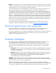
Component identification Front panel components Item Description 1 Serial label pull tab 2 HP c-Class Blade SUV Cable connector 3 Release button 4 Server blade handle Component identification 53
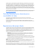
Front panel LEDs and buttons Item Description Status 1 UID LED/button Blue = Identified Blue flashing = Active remote management Off = No active remote management 2 Health LED Green = Normal Amber flashing = Degraded condition Red flashing = Critical condition 3 NIC 1 LED Green = Network linked Green flashing = Network activity Off = No link or activity 4 NIC 2 LED Green = Network linked Green flashing = Network activity Off = No link or activity 5 Hard drive activity LED Green = Activity
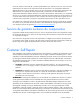
System board components Item Description 1 System board thumbscrew 2 Processor socket 2 (with blank) 3 DIMM slots (6) 4 Hard drive data connector 1 5 Hard drive data connector 2 6 Hard drive power connector 7 USB connector 8 Embedded NICs (2) 9 Mezzanine connector (Type II mezzanine cards only) 10 Enclosure connector 11 System board thumbscrew 12 System maintenance switch 13 System battery 14 Processor socket 1 (populated) The symbols correspond to the symbols located on the i
Position Function Default 5 Password disabled Off 6 Reset configuration Off 7 Reserved Off 8 Reserved Off When the system maintenance switch position 6 is set to the On position, the system is prepared to erase all system configuration settings from both CMOS and NVRAM. CAUTION: Clearing CMOS and/or NVRAM deletes configuration information. Be sure to properly configure the server or data loss could occur.
Specifications Environmental specifications Specification Value Temperature range* Operating** 10°C to 35°C (50°F to 95°F) Non-operating -30°C to 60°C (-22°F to 140°F) Relative humidity (noncondensing) Operating 10% to 90% Non-operating 5% to 95% Maximum wet bulb temperature (noncondensing) Operating 28.0°C (82.4°F) Non-operating 38.7°C (101.
Acronyms and abbreviations CSR Customer Self Repair HP SIM HP Systems Insight Manager iLO 2 Integrated Lights-Out 2 IML Integrated Management Log NVRAM non-volatile memory PSP ProLiant Support Pack RBSU ROM-Based Setup Utility SUV serial, USB, video UID unit identification Acronyms and abbreviations 58
Index A access panel 16, 24 additional information 50 air baffle 16, 24 B batteries, replacing 26 battery 16, 26, 55 battery tray 26 buttons 53 C cables 47 cabling 47 cabling, hard drive 47 cautions 21 component identification 53 components 16, 53 connectors 53 CSR (customer self repair) 5, 16 customer self repair (CSR) 5, 16 D diagnostic tools 50 diagnostics utility 50 DIMM banks, identification 55 DIMM banks, population 24 DIMM slot locations 55 DIMMs 16, 24, 55 E electrostatic discharge 21 enclosure
M mechanical components 16 memory 24 mezzanine board connectors 55 mezzanine card 16, 25 mezzanine connector covers 16 mezzanine connectors 55 N NIC (network interface card) 55 NIC LEDs 54 NIC mezzanine 16 P part numbers 16 plastics kit 16 power button LED 54 Power On/Standby button 54 powering down 23 preparation procedures 22 processor socket 33, 55 processors 16, 33, 55 R release button 16, 45, 53 removal and replacement procedures 21 removing mezzanine boards 25 removing the server blade 23 removing