HP ProLiant BL2x220c G6 Server Blade Maintenance and Service Guide Abstract This guide is for an experienced service technician. HP assumes you are qualified in the servicing of computer equipment and trained in recognizing hazards in products with hazardous energy levels and are familiar with weight and stability precautions for rack installations.
© Copyright 2009, 2011 Hewlett-Packard Development Company, L.P. The information contained herein is subject to change without notice. The only warranties for HP products and services are set forth in the express warranty statements accompanying such products and services. Nothing herein should be construed as constituting an additional warranty. HP shall not be liable for technical or editorial errors or omissions contained herein. Microsoft and Windows are U.S.
Contents Customer self repair ...................................................................................................................... 5 Parts only warranty service ............................................................................................................................ 5 Illustrated parts catalog ............................................................................................................... 16 Server blade components ........................................
Specifications ............................................................................................................................. 61 Environmental specifications ........................................................................................................................ 61 Server blade specifications .......................................................................................................................... 61 Acronyms and abbreviations .................................
Customer self repair HP products are designed with many Customer Self Repair (CSR) parts to minimize repair time and allow for greater flexibility in performing defective parts replacement. If during the diagnosis period HP (or HP service providers or service partners) identifies that the repair can be accomplished by the use of a CSR part, HP will ship that part directly to you for replacement. There are two categories of CSR parts: • Mandatory—Parts for which customer self repair is mandatory.
Obligatoire - Pièces pour lesquelles la réparation par le client est obligatoire. Si vous demandez à HP de remplacer ces pièces, les coûts de déplacement et main d'œuvre du service vous seront facturés. Facultatif - Pièces pour lesquelles la réparation par le client est facultative. Ces pièces sont également conçues pour permettre au client d'effectuer lui-même la réparation.
In base alla disponibilità e alla località geografica, le parti CSR vengono spedite con consegna entro il giorno lavorativo seguente. La consegna nel giorno stesso o entro quattro ore è offerta con un supplemento di costo solo in alcune zone. In caso di necessità si può richiedere l'assistenza telefonica di un addetto del centro di supporto tecnico HP. Nel materiale fornito con una parte di ricambio CSR, HP specifica se il cliente deve restituire dei componenti.
defekte Teil nicht zurückschicken, kann HP Ihnen das Ersatzteil in Rechnung stellen. Im Falle von Customer Self Repair kommt HP für alle Kosten für die Lieferung und Rücksendung auf und bestimmt den Kurier-/Frachtdienst. Weitere Informationen über das HP Customer Self Repair Programm erhalten Sie von Ihrem Servicepartner vor Ort. Informationen über das CSR-Programm in Nordamerika finden Sie auf der HP Website unter (http://www.hp.com/go/selfrepair).
enviara el componente defectuoso requerido, HP podrá cobrarle por el de sustitución. En el caso de todas sustituciones que lleve a cabo el cliente, HP se hará cargo de todos los gastos de envío y devolución de componentes y escogerá la empresa de transporte que se utilice para dicho servicio. Para obtener más información acerca del programa de Reparaciones del propio cliente de HP, póngase en contacto con su proveedor de servicios local.
Neem contact op met een Service Partner voor meer informatie over het Customer Self Repair programma van HP. Informatie over Service Partners vindt u op de HP website (http://www.hp.com/go/selfrepair). Garantieservice "Parts Only" Het is mogelijk dat de HP garantie alleen de garantieservice "Parts Only" omvat. Volgens de bepalingen van de Parts Only garantieservice zal HP kosteloos vervangende onderdelen ter beschikking stellen.
No caso desse serviço, a substituição de peças CSR é obrigatória. Se desejar que a HP substitua essas peças, serão cobradas as despesas de transporte e mão-de-obra do serviço.
Customer self repair 12
Customer self repair 13
Customer self repair 14
Customer self repair 15
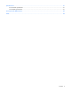
Illustrated parts catalog Server blade components Item Description Spare part number Customer self repair (on page 5) 1 Processor — — a) Intel® Xeon® E5502 quad-core processor** 490075-001 Mandatory1 b) Intel® Xeon® E5504 quad-core processor* ** 490074-001 Mandatory1 d) Intel® Xeon® E5506 quad-core processor* ** 506013-001 Mandatory1 c) Intel® Xeon® E5520 quad-core processor* ** 490073-001 Mandatory1 c) Intel® Xeon® E5530 quad-core processor* ** 490072-001 Mandatory1 e) Intel® Xeon®
Item 2 3 4 5 Description Spare part number Customer self repair (on page 5) j) Intel® Xeon® X5560 quad-core processor* ** 490069-001 Mandatory1 k) Intel® Xeon® X5550 quad-core processor* ** 490070-001 Mandatory1 l) Intel® Xeon® E5620 processor* ** 594887-001 Mandatory1 m) Intel® Xeon® E5630 processor* ** 594886-001 Mandatory1 n) Intel® Xeon® E5640 processor* ** 594885-001 Mandatory1 o) Intel® Xeon® X5650 processor* ** 594884-001 Mandatory1 p) Intel® Xeon® X5660 processor* ** 59488
Item Description Spare part number Customer self repair (on page 5) d) Sever B, processor 2 548422-001 Mandatory1 6 System battery, lithium, 3V* 234556-001 Mandatory1 7 SD card adapter 586010-001 Mandatory1 8 Mezzanine card options* — — 9 a) Emulex LPe1105-HP 4Gb FC HBA for HP c-Class BladeSystem 405921-001 Mandatory1 b) QLogic QMH2462 4Gb FC HBA for HP c-Class BladeSystem 405920-001 Mandatory1 c) HP NC325m PCI Express Quad Port Gigabit Server Adapter for c-Class BladeSystem d) HP NC
No: Non CSR—Alcuni componenti HP non sono progettati per la riparazione da parte del cliente. Per rispettare la garanzia, HP richiede che queste parti siano sostituite da un centro di assistenza autorizzato. Tali parti sono identificate da un “No” nel Catalogo illustrato dei componenti. 3 Mandatory: Zwingend—Teile, die im Rahmen des Customer Self Repair Programms ersetzt werden müssen. Wenn Sie diese Teile von HP ersetzen lassen, werden Ihnen die Versand- und Arbeitskosten für diesen Service berechnet.
Illustrated parts catalog 20
Removal and replacement procedures Required tools You need the following items for some procedures: • T-15 Torx screwdriver • Diagnostics Utility Safety considerations Before performing service procedures, review all the safety information. Preventing electrostatic discharge To prevent damaging the system, be aware of the precautions you need to follow when setting up the system or handling parts.
Symbols on equipment The following symbols may be placed on equipment to indicate the presence of potentially hazardous conditions. This symbol indicates the presence of hazardous energy circuits or electric shock hazards. Refer all servicing to qualified personnel. WARNING: To reduce the risk of injury from electric shock hazards, do not open this enclosure. Refer all maintenance, upgrades, and servicing to qualified personnel. This symbol indicates the presence of electric shock hazards.
• Press and release the server A and server B Power On/Standby buttons. This method initiates a controlled shutdown of applications and the OS before the server blade enters standby mode. • Press and hold the server A and server B Power On/Standby buttons for more than 4 seconds to force the server blade to shut down. This method forces the server blade to enter standby mode without properly exiting applications and the OS. It provides an emergency shutdown method in the event of a hung application.
Access the internal server components To access internal server components, remove server B assembly from server A assembly. WARNING: To reduce the risk of personal injury from hot surfaces, allow the drives and the internal system components to cool before touching them. CAUTION: To prevent damage to electrical components, properly ground the server blade before beginning any installation procedure. Improper grounding can cause ESD.
Install the server B assembly For access component identification, see "Access components (on page 60)." 1. Engage the front edge of the server B assembly with the front edge of the server A assembly. CAUTION: To avoid possible damage to mezzanine card cables, route any cables so that they do not become pinched when the server B assembly is installed. IMPORTANT: To avoid possible damage to the serial label pull tab, extend the serial label pull tab approximately 1 cm (0.
WARNING: To reduce the risk of personal injury from hot surfaces, allow the drives and the internal system components to cool before touching them. To remove the component: 1. Power down the server blade (on page 22). 2. Remove the server blade (on page 23). 3. Access the internal server components (on page 24). 4. Remove the hard drive assembly: o To remove the hard drive assembly from the server A assembly, remove the T-10 hard drive carrier screw and loosen the two system board thumbscrews.
o 5. To remove the hard drive assembly from the server B assembly, remove the T-10 hard drive carrier screw and then remove the hard drive assembly. Remove the hard drive from the carrier. CAUTION: To avoid damage to the hard drive, use the retaining screw to lower the hard drive assembly into position. To replace the component, reverse the removal procedure. DIMMs To remove the component: 1. Power down the server blade (on page 22). 2. Remove the server blade (on page 23). 3.
4. Open the DIMM slot latches. 5. Remove the DIMM. To replace the component, reverse the removal procedure. SD card adapter WARNING: To reduce the risk of personal injury from hot surfaces, allow the drives and the internal system components to cool before touching them. To remove the component: 1. Power down the server blade (on page 22). 2. Remove the server blade (on page 23). 3. Access the internal server components (on page 24). 4. Remove the SD card adapter.
Heatsink WARNING: To reduce the risk of personal injury from hot surfaces, allow the drives and the internal system components to cool before touching them. To remove the component: 1. Power down the server blade (on page 22). 2. Remove the server blade (on page 23). 3. Access the internal server components (on page 24). CAUTION: To avoid damage to the system board, alternate removing or tightening the heatsink screws. 4. Remove the heatsink.
2. Remove the thermal interface protective cover from the heatsink. 3. Align and install the heatsink. Alternate tightening the screws until the heatsink is seated properly. 4. Install the server B assembly (on page 25). 5. Install the server blade (on page 25). Processor WARNING: To reduce the risk of personal injury from hot surfaces, allow the drives and the internal system components to cool before touching them.
CAUTION: The heatsink thermal interface media is not reusable and must be replaced if the heatsink is removed from the processor after it has been installed. CAUTION: To avoid damage to the server blade, do not operate the server blade unless both processor sockets are populated with a processor and heatsink. IMPORTANT: When installing the heatsink, align the guide pins on the processor retention bracket with the alignment holes in the heatsink. NOTE: Do not discard the processor protective cover.
5. Open the processor locking lever and the processor socket retaining bracket. 6. Using the processor tool, remove the processor from the system board: a. Line up the processor tool, ensuring the locking lever graphic on the tool is oriented correctly. b. Press in on the plastic tabs, and then place the tool on the processor. c. Release the tabs, and then carefully lift the processor and tool straight up.
7. Carefully rotate the tool, and then push in and release the tabs to secure the processor in the tool. CAUTION: To avoid damage to the processor, do not touch the bottom of the processor, especially the contact area. To replace the component: 1. Carefully insert the processor into the processor installation tool. Handle the processor by the edges only, and do not touch the bottom of the processor, especially the contact area.
2. Be sure the tool is oriented correctly. Align the processor installation tool with the socket, and then install the processor. THE PINS ON THE SYSTEM BOARD ARE VERY FRAGILE AND EASILY DAMAGED. CAUTION: THE PINS ON THE SYSTEM BOARD ARE VERY FRAGILE AND EASILY DAMAGED. To avoid damage to the system board: • Never install or remove a processor without using the processor installation tool. • Do not touch the processor socket contacts.
3. Press and hold the tabs on the processor installation tool to separate it from the processor, and then remove the tool. 4. Close the processor socket retaining bracket and the processor locking lever. CAUTION: Be sure to close the processor socket retaining bracket before closing the processor locking lever. The lever should close without resistance. Forcing the lever closed can damage the processor and socket, requiring system board replacement. 5.
6. Apply all the grease to the top of the processor in the following pattern to ensure even distribution. CAUTION: To avoid damage to the system board, alternate removing or tightening the heatsink screws. 7. Align and install the heatsink. Alternate tightening the screws until the heatsink is seated properly. 8. Install the server B assembly (on page 25). 9. Install the server blade (on page 25).
3. Access the internal server components (on page 24). 4. Disconnect any cables connected to the mezzanine card. 5. Remove the mezzanine card. CAUTION: To prevent damage to the server blade, apply pressure over the mezzanine connector when installing the mezzanine card. Do not apply pressure to the edges of the card. To replace the component, reverse the removal procedure. Server A system board To remove the component: 1. Power down the server blade (on page 22). 2.
8. Open the processor locking lever and the processor socket retaining bracket. 9. Using the processor tool, remove the processor from the system board: a. Line up the processor tool, ensuring the locking lever graphic on the tool is oriented correctly. b. Press in on the plastic tabs, and then place the tool on the processor. c. Release the tabs, and then carefully lift the processor and tool straight up.
10. Carefully rotate the tool, and then push in and release the tabs to secure the processor in the tool. CAUTION: To avoid damage to the processor, do not touch the bottom of the processor, especially the contact area. 11. If installed, remove the hard drive (on page 25). 12. Remove the system board assembly.
To replace the system board: 1. Install the spare system board. Be sure the spools on the chassis are fully engaged in the slots in the system board assembly. CAUTION: Failure to completely open the processor locking lever prevents the processor from seating during installation, leading to hardware damage. 2. Open the processor locking lever and the processor socket retaining bracket. Do not remove the processor socket cover.
3. If the processor has separated from the installation tool, carefully re-insert the processor in the tool. Handle the processor by the edges only, and do not touch the bottom of the processor, especially the contact area.
4. Align the processor installation tool with the socket, and then install the processor. THE PINS ON THE SYSTEM BOARD ARE VERY FRAGILE AND EASILY DAMAGED. CAUTION: THE PINS ON THE SYSTEM BOARD ARE VERY FRAGILE AND EASILY DAMAGED. To avoid damage to the system board: • Never install or remove a processor without using the processor installation tool. • Do not touch the processor socket contacts. • Do not tilt or slide the processor when lowering the processor into the socket.
5. Press the tabs on the processor installation tool to separate it from the processor, and then remove the tool. 6. Close the processor socket retaining bracket and the processor locking lever. The processor socket cover is automatically ejected. Remove the cover. CAUTION: Be sure to close the processor socket retaining bracket before closing the processor locking lever. The lever should close without resistance.
9. Apply all the grease to the top of the processor in the following pattern to ensure even distribution. 10. Align and install the heatsink. Alternate tightening the screws until the heatsink is seated properly. 11. Install all components removed from the failed system board. 12. Record the server serial number and product ID. For the location of the serial number label, see "Server A system board components (on page 57)." 13. Install the server B assembly (on page 25). 14.
Warning: The serial number should ONLY be modified by qualified personnel. This value should always match the serial number located on the chassis. 5. Press the Enter key to clear the warning. 6. Enter the serial number and press the Enter key. 7. Select Product ID. The following warning appears: Warning: The Product ID should ONLY be modified by qualified personnel. This value should always match the Product ID on the chassis. 8. Enter the product ID and press the Enter key. 9.
9. Open the processor locking lever and the processor socket retaining bracket. 10. Using the processor tool, remove the processor from the system board: a. Line up the processor tool, ensuring the locking lever graphic on the tool is oriented correctly. b. Press in on the plastic tabs, and then place the tool on the processor. c. Release the tabs, and then carefully lift the processor and tool straight up.
11. Carefully rotate the tool, and then push in and release the tabs to secure the processor in the tool. CAUTION: To avoid damage to the processor, do not touch the bottom of the processor, especially the contact area. To replace the system board: CAUTION: Failure to completely open the processor locking lever prevents the processor from seating during installation, leading to hardware damage. 1. Open the processor locking lever and the processor socket retaining bracket.
2. If the processor has separated from the installation tool, carefully re-insert the processor in the tool. Handle the processor by the edges only, and do not touch the bottom of the processor, especially the contact area.
3. Align the processor installation tool with the socket, and then install the processor. THE PINS ON THE SYSTEM BOARD ARE VERY FRAGILE AND EASILY DAMAGED. CAUTION: THE PINS ON THE SYSTEM BOARD ARE VERY FRAGILE AND EASILY DAMAGED. To avoid damage to the system board: • Never install or remove a processor without using the processor installation tool. • Do not touch the processor socket contacts. • Do not tilt or slide the processor when lowering the processor into the socket.
4. Press the tabs on the processor installation tool to separate it from the processor, and then remove the tool. 5. Close the processor socket retaining bracket and the processor locking lever. The processor socket cover is automatically ejected. Remove the cover. CAUTION: Be sure to close the processor socket retaining bracket before closing the processor locking lever. The lever should close without resistance.
8. Apply all the grease to the top of the processor in the following pattern to ensure even distribution. 9. Align and install the heatsink. Alternate tightening the screws until the heatsink is seated properly. 10. Install all components removed from the failed system board. 11. Install the serial label pull tab. 12. Record the server serial number and product ID. For the location of the serial number label, see "Server B system board components (on page 58)." 13.
be used by qualified service personnel. This value should always match the serial number sticker located on the chassis. Warning: The serial number should ONLY be modified by qualified personnel. This value should always match the serial number located on the chassis. 5. Press the Enter key to clear the warning. 6. Enter the serial number and press the Enter key. 7. Select Product ID. The following warning appears: Warning: The Product ID should ONLY be modified by qualified personnel.
System battery HP recommends replacing the battery on both server A and server B when either battery is replaced. If the server blade no longer automatically displays the correct date and time, you may need to replace the battery that provides power to the real-time clock. Under normal use, battery life is 5 to 10 years. WARNING: The computer contains an internal lithium manganese dioxide, a vanadium pentoxide, or an alkaline battery pack.
Diagnostic tools Troubleshooting resources The HP ProLiant Servers Troubleshooting Guide provides procedures for resolving common problems and comprehensive courses of action for fault isolation and identification, error message interpretation, issue resolution, and software maintenance on ProLiant servers and server blades. This guide includes problem-specific flowcharts to help you navigate complex troubleshooting processes. To view the guide, select a language: • English (http://www.hp.
• From within Survey Utility • From within operating system-specific IML viewers o For NetWare: IML Viewer o For Windows®: IML Viewer o For Linux: IML Viewer Application • From within the iLO 2 user interface • From within HP Insight Diagnostics (on page 54) For more information, see the Management CD in the HP Insight Foundation suite for ProLiant. USB support and functionality USB support HP provides both standard USB 2.0 support and legacy USB 2.0 support.
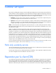
Component identification Front panel components Item Description 1 Server B Power On/Standby button 2 Server B serial label pull tab 3 Server blade release lever 4 Server A serial label pull tab 5 Server A Power On/Standby button Front panel LEDs Item Description Status 1 Server B system power Green = On LED Amber = Standby (auxiliary power available) Off = No power available to server 2 Server B UID LED Blue = Identified Blue flashing = Active remote management Off = No active remote m
Item Description Status 3 Server B health LED Green = Normal Flashing = Booting Amber = Degraded condition Red = Critical condition 4 Server B NIC link and activity LED* Green = Network linked Green flashing = Network activity Off = No link or activity 5 Server A NIC link and Green = Network linked activity LED* Green flashing = Network activity Off = No link or activity 6 Server A health LED Green = Normal Flashing = Booting Amber = Degraded condition Red = Critical condition 7 Server A UID
Item Description 8 Enclosure connector 9 Mezzanine connector 1 10 System maintenance switch 11 DIMM slots (processor 1) 12 Processor socket 2 (populated) 13 Internal USB connector Server B system board components Item Description 1 Hard drive connector 2 Processor socket 1 (populated) 3 System battery 4 DIMM slots (processor 2) 5 Server B serial number label 6 Processor socket 2 (populated) 7 Signal connector 8 System maintenance switch 9 DIMM slots (processor 1) 10 Inter
Server A DIMM slots Server B DIMM slots Mezzanine connector definitions Item PCIe support Mezzanine connector 1 x8, Type I mezzanine card only Server A only Server support Mezzanine connector 2 x8, Type 1 mezzanine card only Server B only A PCIe x8 mezzanine connector supports x16 cards at up to x8 speeds.
System maintenance switch Position Function Default 1 iLO 2 security override Off 2 Configuration lock Off 3 Reserved Off 4 Reserved Off 5 Password disabled Off 6 Reset configuration Off 7 Reserved Off 8 Reserved Off When the system maintenance switch position 6 is set to the On position, the system is prepared to erase all system configuration settings from both CMOS and NVRAM. CAUTION: Clearing CMOS and/or NVRAM deletes configuration information.
Specifications Environmental specifications Specification Value — Temperature range* Operating 10°C to 35°C (50°F to 95°F) Non-operating -30°C to 60°C (-22°F to 140°F) Relative humidity (noncondensing)** — Operating 10% to 90% @ 28°C (82.4°F) Non-operating 5% to 95% @ 38.7°C (101.7°F) Altitude† — Operating 3050 m (10,000 ft) Non-operating 9144 m (30,000 ft) * The following temperature conditions and limitations apply: - All temperature ratings shown are for sea level.
Acronyms and abbreviations CSR Customer Self Repair FC Fibre Channel HBA host bus adapter HP SIM HP Systems Insight Manager iLO 2 Integrated Lights-Out 2 IML Integrated Management Log PCIe peripheral component interconnect express POST Power-On Self Test PXE Preboot Execution Environment RBSU ROM-Based Setup Utility SATA serial ATA SIM Systems Insight Manager Acronyms and abbreviations 62
UID unit identification USB universal serial bus Acronyms and abbreviations 63
Index A M access components 60 accessing internal components management tools 54 mezzanine card 36 mezzanine connectors 57, 59 24 B battery buttons P 53 56 part numbers 16 powering down 22 preparation procedures 22 processor tool 30, 37, 45 processors 30, 57 C cautions 21 components 16, 21, 56 connectors 56 CSR (customer self repair) R 5 removing the server blade ROM legacy USB support D diagnostic tools 54 diagnostics utility 54 dimensions, server 61 DIMM slot locations 59 DIMMs 27 S safety c
U USB support utilities 54 55 W warnings 21 Index 65