HP ProLiant BL30p Server Blade Maintenance and Service Guide May 2004 (First Edition) Part Number 354537-001
© Copyright 2004 Hewlett-Packard Development Company, L.P. The information contained herein is subject to change without notice. The only warranties for HP products and services are set forth in the express warranty statements accompanying such products and services. Nothing herein should be construed as constituting an additional warranty. HP shall not be liable for technical or editorial errors or omissions contained herein. Microsoft and Windows are U.S. registered trademarks of Microsoft Corporation.
Contents About This Guide Audience Assumptions..................................................................................................................................v Technician Notes...........................................................................................................................................v Where to Go for Additional Help.................................................................................................................vi Integrated Management Log ...
Contents Chapter 3 Diagnostic Tools ProLiant BL p-Class Diagnostic Tools ......................................................................................................3-1 Firmware Upgrades for Management Modules .........................................................................................3-3 Chapter 4 Connectors, LEDs, and Switches Connectors .................................................................................................................................................
About This Guide This maintenance and service guide can be used for reference when servicing HP ProLiant BL30p server blades. WARNING: To reduce the risk of personal injury from electric shock and hazardous energy levels, only authorized service technicians should attempt to repair this equipment. Improper repairs can create conditions that are hazardous. Audience Assumptions This guide is for service technicians.
About This Guide CAUTION: To properly ventilate the system, you must provide at least 7.6 cm (3.0 in.) of clearance at the front and back of the server. CAUTION: The computer is designed to be electrically grounded (earthed). To ensure proper operation, plug the AC power cord into a properly grounded AC outlet only. NOTE: Any indications of component replacement or printed wiring board modifications may void any warranty.
About This Guide Telephone Numbers For the name of the nearest HP authorized reseller: • In the United States, call 1-800-345-1518. • In Canada, call 1-800-263-5868. For HP technical support: • In the United States and Canada, call 1-800-633-3300. • Outside the United States and Canada, refer to www.hp.
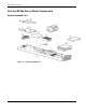
1 Illustrated Parts Catalog This chapter provides illustrated parts and spare parts lists for the HP ProLiant BL30p server blade components. Refer to Table 1-1 for the names of referenced spare parts.
Illustrated Parts Catalog ProLiant BL30p Server Blade Components System Exploded View Figure 1-1: System exploded view 1-2 HP ProLiant BL30p Server Blade Maintenance and Service Guide
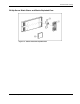
Illustrated Parts Catalog BL30p Server Blade Sleeve and Blanks Exploded View Figure 1-2: Sleeve and blanks exploded view HP ProLiant BL30p Server Blade Maintenance and Service Guide 1-3
Illustrated Parts Catalog Server Blade Spare Parts List Table 1-1: Server Blade Spare Parts List Item Description Spare Part Number Mechanical Components 1 System board assembly 1a Heatsinks (2) * 1b Server blade handle screw and spring* 361743-001 System Components 2 Processors 2a Intel XeonTM 3.06-GHz processor with 512-KB cache (includes one heatsink) 333055-001 2b Intel Xeon 3.2-GHz processor with 1-MB cache (includes one heatsink) * 348272-001 2c Intel Xeon 3.
Illustrated Parts Catalog Table 1-1: Server Blade Spare Parts List continued Item Description Spare Part Number Options 12 Dual Port Fibre Channel Adapter 361744-001 13 Hard drive, 60-GB 361751-001 14 RJ-45 Patch Panel 2, with Fibre Channel support * 322299-001 15 Transceiver, 2-GB, Fibre Channel * 229204-001 16 GbE2 Interconnect Switch * 321148-001 17 ProLiant BL30p blade sleeve cover 361881-001 18 ProLiant BL30p blade sleeve board 361746-001 * Not shown HP ProLiant BL30p Server B
2 Removal and Replacement Procedures This chapter provides subassembly/module-level removal and replacement procedures for system components. After completing all necessary removal and replacement procedures, verify that all components operate properly by running the appropriate diagnostic software: • For server blade components, run the Server Diagnostics Utility, available from the HP website: www.hp.com • For server blade enclosure and power enclosure components, run the infrastructure diagnostics.
Removal and Replacement Procedures WARNING: To reduce the risk of personal injury from hot surfaces, allow the internal system components to cool before touching them. CAUTION: When performing non-hot-plug operations, you must power down the server blade and/or the system. However, it may be necessary to leave the server blade powered up when performing other operations, such as hot-plug installations or troubleshooting.
Removal and Replacement Procedures WARNING: To reduce the risk of shock or injury from high-current electrical energy, do not reach into a power supply enclosure once it has been installed in a rack and connected to a power source. Do not touch the connectors within the power supply enclosure once it has been installed.
Removal and Replacement Procedures Server Blade Preparation To service any internal server blade component, you must power down the server blade and remove it from the server blade enclosure. NOTE: When removing a server blade, it is not necessary to remove the blade sleeve from the enclosure. CAUTION: Electrostatic discharge can damage electronic components. Be sure you are properly grounded before beginning any installation procedure.
Removal and Replacement Procedures 3. Remove the server blade from the server blade enclosure: a. Press the release button (1). b. Open the lever (2). c. Grasp the lever and slide the server blade from the enclosure (3). Place a hand under the server blade to support it as you remove it from the enclosure. NOTE: When removing a server blade, it is not necessary to remove the blade sleeve from the enclosure. Figure 2-1: Removing the server blade from the blade sleeve in the server blade enclosure d.
Removal and Replacement Procedures Hard Drives To replace a hard drive: 1. Back up the server blade data. 2. Remove the server blade from the server blade enclosure. Refer to “Server Blad e Preparation” in this chapter.
Removal and Replacement Procedures Figure 2-4: Removing a hard drive from the drive cage assembly Figure 2-5: Removing the center plate from the drive cage assembly HP ProLiant BL30p Server Blade Maintenance and Service Guide 2-7
Removal and Replacement Procedures Figure 2-6: Removing a second hard drive IMPORTANT: Be sure the hard drive label is on the top side of the hard drive when installed in the drive cage assembly.
Removal and Replacement Procedures Figure 2-8: Replacing the center plate NOTE: Be sure that the jumper on the drive is set to Cable Select (CS) so that the drive device ID is determined by the cable. IMPORTANT: Be sure the center plate is oriented as in the following figure. The pins must be pointed down when being installed into the main cage.
Removal and Replacement Procedures Figure 2-10: Reinstalling the drive cage assembly 2-10 HP ProLiant BL30p Server Blade Maintenance and Service Guide
Removal and Replacement Procedures DIMMs To remove a DIMM: 1. Power down the server blade and remove it from the server blade enclosure. Refer to the “Server Blad e Preparation” section in this chapter. NOTE: The server blade ships with one 1-GB DIMM installed in slot 1. 2. Open the DIMM slot latches (1). 3. Remove the DIMM from the slot (2). Figure 2-11: Removing a DIMM IMPORTANT: For proper DIMM configuration, refer to the HP ProLiant BL30p Server Blade Setup and Installation Guide.
Removal and Replacement Procedures Processors and Heatsinks CAUTION: If installing only one processor in the server blade, be sure to install a processor blank in processor socket 2. A processor blank may need to be removed before installing an additional processor.
Removal and Replacement Procedures To remove a processor: 1. Remove the heatsink (3). CAUTION: The heatsink is not reusable and must be discarded if removed from the processor after application.
Removal and Replacement Procedures 2. Remove the processor (2). Figure 2-14: Removing the processor To replace the processor: CAUTION: When installing the processor into the socket, be sure that the locking lever is raised to avoid damaging pins. 1. Align the processor and install the processor into the socket (1). 2. Close the processor locking lever (2).
Removal and Replacement Procedures CAUTION: Be sure that the processor socket locking lever is closed. Do not force the lever closed after the processor installation; it should close without resistance. Forcing the lever closed may result in damage to the processor and its socket, requiring replacement of the system board. 3. Remove the thermal interface media cover from the heatsink.
Removal and Replacement Procedures 4. Align the heatsink and install onto processor (1). 5. Close the heatsink brace (2). 6. Close the heatsink locking lever (3). Figure 2-17: Replacing the heatsink CAUTION: If installing only one processor in the server blade, be sure to install a processor blank in processor socket 2.
Removal and Replacement Procedures Fan Assembly To remove the fan assembly: 1. Power down the server blade and remove it from the server blade enclosure. Refer to the “Server Blad e Preparation” section in this chapter. 2. Lay the server blade on a flat, stable surface. 3. Disconnect the two fan cables from the system board. Figure 2-18: Disconnecting fan cables 4. Squeeze the retaining clips on the fan assembly (1) and lift the fan assembly from the retaining brackets (2).
Removal and Replacement Procedures Dual Port Fibre Channel Adapter To remove the Dual Port Fibre Channel (FC) adapter: 1. Power down the server blade and remove it from the server blade enclosure. Refer to the “Server Blad e Preparation” section in this chapter. 2. Loosen the thumbscrews (1). 3. Remove the FC Adapter (2). Figure 2-20: Removing the Dual Port Fibre Channel adapter Reverse steps 1 through 3 to replace the FC adapter.
Removal and Replacement Procedures NIC Riser Board To remove the NIC riser board: 1. Power down the server blade and remove it from the server blade enclosure. Refer to the “Server Blad e Preparation” section in this chapter. 2. Remove the FC adapter. Refer to “Dual Port Fibre Channel Adapter” in this chapter. 3. Loosen the thumbscrews (1). 4. Remove the NIC riser board (2). Figure 2-21: Removing the NIC riser board Reverse steps 1 through 4 to replace the NIC riser board.
Removal and Replacement Procedures Power Converter Module To remove the power converter module: 1. Power down the server blade and remove it from the server blade enclosure. Refer to the “Server Blad e Preparation” section in this chapter. 2. Remove the FC adapter. Refer to “Dual Port Fibre Channel Adapter” in this chapter. 3. Remove the NIC riser board. Refer to “NIC Rise r Board” in this chapter. 4. Release the two clips securing the power converter module to the system board (1). 5.
Removal and Replacement Procedures Power Button/LED Cable The power button/LED cable is included in the cable kit. To remove the power button/LED cable: 1. Power down the server blade and remove it from the server blade enclosure. Refer to the “Server Blad e Preparation” section in this chapter. 2. Remove the cable. Figure 2-23: Removing the power button/LED cable Use the same connectors in the illustration to replace the power button/LED cable.
Removal and Replacement Procedures Server Blade Handle The server blade handle contains a serial number that maintains the original server blade warranty. In the event that the system board assembly is replaced, the original handle must be removed, and attached to the new server blade system board assembly. To remove the server blade handle: 1. Power down the server blade and remove it from the server blade enclosure. Refer to “Server Blad e Preparation” in this chapter. 2.
Removal and Replacement Procedures System Board Assembly To replace the system board assembly: 1. Power down the server blade and remove it from the server blade enclosure. Refer to “Server Blad e Preparation” in this chapter. 2. Remove the drive cage assembly. Refer to “Hard Drives” in this chapter. 3. Remove the DIMMs. Refer to “DIMMs” in this chapter. 4. Remove the processors and heatsinks. Refer to “Proces sors and Heatsinks” in this chapter. 5. Remove the fan assembly.
Removal and Replacement Procedures Battery If the server blade no longer automatically displays the correct date and time, you may need to replace the battery that provides power to the real-time clock. Under normal use, battery life is 5 to 10 years. WARNING: This server blade contains either an internal lithium manganese dioxide or a vanadium pentoxide battery. A risk of fire and burns exists if the battery pack is not handled properly.
Removal and Replacement Procedures To remove the system board battery: 1. Power down the server blade and remove it from the server blade enclosure. Refer to “Server Blad e Preparation” in this chapter. 2. Locate the battery holder on the system board. 3. Remove the existing battery by pushing the tab aside and pulling the battery straight up. Figure 2-25: Removing the system board battery To install the system board battery, push it into the socket until the tab locks in place.
Removal and Replacement Procedures ProLiant BL30p Blade Sleeve Removing the Blade Sleeve CAUTION: Be sure that the ProLiant BL30p server blade and sleeve are installed in a server blade enclosure with enhanced backplane components. Installing a ProLiant BL30p server blade or sleeve in an enclosure without enhanced backplane components can damage the power subsystem. The blade sleeve is released from the enclosure when both BL30p server blades are removed from it. To remove a blade sleeve: 1.
Removal and Replacement Procedures Removing the Blade Sleeve Board To remove the blade sleeve board: 1. With the blade sleeve on a flat surface, remove the access panel from the blade sleeve. Figure 2-27: Removing the blade sleeve access panel 2. Loosen the thumbscrews on the outside of the blade sleeve (1). 3. Remove the screws from the blade sleeve board (2), and remove the blade sleeve (3). Figure 2-28: Removing the blade sleeve board Reverse steps 1 through 3 to replace the blade sleeve board.
Removal and Replacement Procedures Server Blade Blanks CAUTION: Always populate server blade enclosure bays with either a server blade, a populated blade sleeve, or a server blade blank. Operating the enclosure unpopulated results in improper airflow and improper cooling that can lead to thermal damage. Two sizes of blanks exist for the HP ProLiant BL p-Class System.
Removal and Replacement Procedures Figure 2-30: Removing a 3U server blade blank from a blade sleeve To replace a server blade blank, align the blank with the empty bay and slide it in until the blank is fully seated.
3 Diagnostic Tools ProLiant BL p-Class Diagnostic Tools Use the following tools to diagnose problems, test hardware, and monitor and manage system operations. Table 3-1: Diagnostic Tools Tool Description How to run the tool Automatic Server Recovery (ASR) ASR automatically restarts the server blade after a catastrophic operating system failure. Run RBSU and set ASR to enable this tool.
Diagnostic Tools Table 3-1: Diagnostic Tools continued Tool Description How to run the tool HP Systems Insight Manager (HP SIM) HP SIM provides comprehensive management of ProLiant BL30p server blades, maximizing system availability and optimizing IT staff efficiency. HP SIM allows systems administrators to quickly identify hardware failures, isolate and update systems running out-of-date system software, and easily access onboard management resources. In addition, HP SIM version 4.
Diagnostic Tools Table 3-1: Diagnostic Tools continued Tool Description How to run the tool HP ProLiant Essentials Rapid Deployment Pack (RDP) The optional RDP is the preferred method for rapid, high-volume server blade deployments. The RDP includes Altiris eXpress Deployment Server and the SmartStart Scripting Toolkit. Install the CD in the CD-ROM drive of the administrator workstation or client PC and refer to the documentation that ships with the software.
4 Connectors, LEDs, and Switches Connectors ProLiant BL30p Server Blade Front Panel Connectors The server blade has one front panel connector for configuration and troubleshooting purposes. Figure 4-1: ProLiant BL30p I/O port NOTE: The rear iLO port is disabled when iLO is accessed through the I/O port on the front panel.
Connectors, LEDs, and Switches Rear Panel Connectors Use Figure 4-2 and Table 4-1 to identify ProLiant BL30p server blade rear panel connectors.
Connectors, LEDs, and Switches System Board Components and Connectors Use Figure 4-3 and Table 4-2 to identify ProLiant BL30p system board components and connectors.
Connectors, LEDs, and Switches Figure 4-3: ProLiant BL30p system board components and connectors 4-4 HP ProLiant BL30p Server Blade Maintenance and Service Guide HP
Connectors, LEDs, and Switches Table 4-2: System Board Components and Connectors Item Description 1 Power button/LED board connector (under the fan assembly) 2 Fan assembly connectors (2) 3 System Maintenance Switch (SW1) 4 Processor socket 2 5 Adapter card connectors (2) 6 Battery 7 Power converter module 8 DIMM slots (2) 9 Processor socket 1 (populated) 10 Hard drive cable connector 11 Fan assembly 12 Drive cage assembly Local I/O Cable CAUTION: Disconnect the local I/O cable fr
Connectors, LEDs, and Switches Refer to Figure 4-4 to identify the I/O icon. Refer to Figure 4-5 and Table 4-3 to identify local I/O cable connectors.
Connectors, LEDs, and Switches Figure 4-5: Local I/O cable connectors Table 4-3: Local I/O Cable Connectors Item Description 1 Server blade connector 2 Video connector 3 USB connector (2) 4 Serial connector 5 iLO RJ-45 (10/100 Ethernet) connector IMPORTANT: Completely log out of the current iLO session before removing the local I/O cable.
Connectors, LEDs, and Switches LEDs ProLiant BL30p Server Blade Front Panel Six LEDs on the front of the server blade indicate server status. Use Figure 4-6 and Table 4-4 to identify LED locations and functions.
Connectors, LEDs, and Switches Table 4-4: ProLiant BL30p Server Blade Front Panel LEDs Item 1 LED Description Status Server Blade Unit Identification (UID) LED Blue = Flagged Blue flashing = Management mode Off = No remote management 2 Server Blade Health LED Green = Normal status Flashing = Booting Amber = Degraded status Red = Critical status Green = Linked to network 3 Server Blade NIC 1 LED* 4 Server Blade NIC 2 LED* 5 Server Blade Hard Drive Activity LED Green/Flashing = Activity Power
Connectors, LEDs, and Switches Switches and Buttons Use the following sections to identify the locations and functions of push-button and system switches. Power On/Standby Button Setting the server blade Power On/Standby button to the standby position removes power from most areas of the server blade. This process may take 30 seconds, during which time some internal circuitry remains active.
Connectors, LEDs, and Switches System Switches System switches enable you to change certain settings or to perform advanced diagnostic procedures. Use Figure 4-7 to identify the system maintenance switch location. Figure 4-7: Server blade system switches Refer to the HP ProLiant BL30p Setup and Installation Guide or to the hood label on the server blade for the switch functions.
Connectors, LEDs, and Switches NMI Switch Crash dump analysis is an essential part of eliminating reliability problems such as hangs or crashes in operating systems, device drivers, and applications. Crashes can freeze a system, requiring you to do a hard reset. Resetting the system erases any information that supports root cause analysis. Systems running Microsoft Windows 2000 or 2003 experience a blue screen trap when the operating system crashes.
Connectors, LEDs, and Switches 7. Repeat steps 1 through 3. 8. Change position 6 of SW1 to off. 9. Repeat steps 5 through 7. IMPORTANT: When the server blade boots after NVRAM is cleared, a delay of up to 2 minutes is normal. During this delay, the system appears non-functional. Do not attempt any procedures during the delay.
Connectors, LEDs, and Switches Accessing the Redundant ROM If the system ROM is corrupted, you can set the system to use the backup version or redundant ROM. To use the redundant ROM: 1. Power down the server blade: — Press the Power On/Standby button on the front of the server blade. — Use the virtual power button feature in the iLO remote console. 2. Disconnect the server blade from all power sources: — Remove the server blade from the enclosure and set it on a flat, level surface.
5 Server Blade Specifications This appendix provides operating and performance specifications for the following: • ProLiant BL30p Server Blade • ATA Hard Drive Assembly ProLiant BL30p Server Blade Table 5-1: Operating and Performance Specifications for ProLiant BL30p Server Blade Dimensions Width 12.0 cm (4.72 in) Depth 64.4 cm (25.35 in) Height 4.1 cm (1.61 in) Weight (maximum) Temperature range 4.
Server Blade Specifications ATA Hard Drive Table 5-2: ATA Hard Drive Specifications Feature 60-GB/5400 RPM Hard Drive Capacity 60,000 MB Height 9.5 mm (0.37 in) Size 5-2 Width 70mm (2.76 in) Height 9.5mm (.37 in) Diameter 100mm (3.94 in) Interface ATA-5 (IDE) 100 MB/s Transfer rate 17.
Index A D access panel, spare part number 1-4 ASR See Automatic Server Recovery (ASR) Automatic Server Recovery (ASR) access 3-1 description 3-1 DC-to-DC converter, location 4-5 diagnostic tools 3-1 Diagnostics Utility, description 3-1 DIMMs removing 2-11 replacing 2-11 drive cage assembly, spare part number 1-4 Dual Port Fibre Channel adapter removing 2-18 replacing 2-18 spare part number 1-5 Dual Port Fibre Channel adapter connectors, location 4-5 B battery disposal 2-24 disposal, caution 2-24 locati
Index H M handle removing 2-22 replacing 2-22 hard drive spare part number 1-5 specifications 5-2 hard drive connector, location 4-5 hardware kit, spare part number 1-4 heatsink, removing 2-13 help resources vi hot 2-3 hot-plug SCSI hard drives, removing 2-6 HP authorized reseller vii HP ProLiant BL p-Class System Setup and Installation Guide 3-2 HP ProLiant Essentials Rapid Deployment Pack access 3-3 description 3-3 HP SIM See HP Systems Insight Manager HP Systems Insight Manager access 3-2 description
Index replacing battery 2-25 blade sleeve board 2-27 DIMMs 2-11 Dual Port Fibre Channel adapter 2-18 fan assembly 2-17 handle 2-22 NIC riser board 2-19 power button/LED cable 2-21 power converter module 2-20 processor assembly 2-14 server blade blank 2-29 server blades 2-5 system board assembly 2-23 RJ-45 Patch Panel 2, spare part number 1-5 ROM-Based Setup Utility (RBSU) access 3-3 description 3-3 ROMPaq Utility access 3-2 description 3-2 S server blade cautions 2-1 LEDs 4-8 powering down 2-4 removing 2-