HP ProLiant BL35p Server Blade User Guide August 2006 (Fourth Edition) Part Number 379104-004
© Copyright 2005, 2006 Hewlett-Packard Development Company, L.P. The information contained herein is subject to change without notice. The only warranties for HP products and services are set forth in the express warranty statements accompanying such products and services. Nothing herein should be construed as constituting an additional warranty. HP shall not be liable for technical or editorial errors or omissions contained herein. Microsoft and Windows are U.S.
Contents Component identification ............................................................................................................... 6 Server blade components ........................................................................................................................... 6 Front panel components and LEDs...................................................................................................... 6 Internal components..........................................................
HP ROM-Based Setup Utility............................................................................................................ 54 Re-entering the server serial number and product ID ........................................................................... 55 Management tools................................................................................................................................... 56 Automatic Server Recovery ..................................................................
Declaration of conformity for products marked with the FCC logo, United States only....................................... 80 Modifications.......................................................................................................................................... 81 Cables ................................................................................................................................................... 81 Canadian notice (Avis Canadien)..........................................
Component identification In this section Server blade components .......................................................................................................................... 6 Sleeve board and server blade LED locations .............................................................................................. 9 Local I/O cable .....................................................................................................................................
Item Description Status 4 NIC 2 LED* Green = Network linked Green flashing = Network activity Off = No link or activity 5 Hard drive activity LED Green/Flashing = Activity Off = No activity 6 Power On/Standby button LED Green = On Amber = Standby (auxiliary power available) Off = Off 7 Local I/O port** — * Actual NIC numeration depends on several factors, including the operating system installed on the server blade.
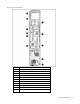
Internal components Item Description 1 Fan assembly connectors (2) 2 Processor socket 2 3 DIMM bank A (populated) 4 Adapter card connectors (2) 5 Battery 6 Processor socket 1 (populated) 7 DIMM bank B 8 Hard drive cable connector 9 System maintenance switch (SW1) 10 Fan assembly 11 Hard drive cage Component identification 8
System maintenance switch Position Default Function S1 Off Off = iLO security is enabled. On = iLO security is disabled. S2 Off Off = System configuration can be changed. On = System configuration is locked. S3 Off Reserved S4 Off Reserved S5 Off Off = Power-on password is enabled. On = Power-on password is disabled.
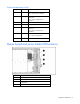
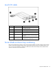
Local I/O cable Item Connector Description 1 Local I/O For connecting to the local I/O port on the server blade front panel 2 Video For connecting a video monitor 3 USB 1 For connecting a USB device 4 USB 2 For connecting a USB device 5 Serial For trained personnel to connect a null-modem serial cable and perform advanced diagnostic procedures 6 iLO RJ-45 (10/100 Ethernet) For connecting an Ethernet to the server blade iLO interface from a client device Server blade enclosure bay numbe
IMPORTANT: When looking at the rear of the enclosure, server blade bay numbering is reversed. Server blade enclosure compatibility The HP ProLiant BL35p Server Blades require the support of an HP BladeSystem p-Class sleeve in a server blade enclosure with enhanced backplane components (enhanced server blade enclosure). The enhanced server blade enclosure also provides a single rear iLO connector for single-cable remote management of all installed HP ProLiant BL35p Server Blades.
Operations In this section Power up the server blade....................................................................................................................... 12 Power down the server blade .................................................................................................................. 12 Remove the server blade .........................................................................................................................
IMPORTANT: When the server blade is in standby mode, auxiliary power is still being provided. To remove all power from the server blade, remove the server blade from the server blade enclosure. Removing the sleeve from the server blade enclosure is not necessary. IMPORTANT: Remote power procedures require the most recent firmware for the power enclosure and server blade enclosure management modules. For the most recent firmware, refer to the HP website (http://www.hp.com/go/support).
Setup In this section Installing the HP BladeSystem components................................................................................................. 14 Verifying system components ................................................................................................................... 14 Connecting to the network....................................................................................................................... 14 Installing server blade options.......................
Using the diagnostic station The diagnostic station provides a method to power up a server blade outside of a server blade enclosure for testing and diagnostic purposes. When using the HP ProLiant BL35p Server Blade with the diagnostic station, observe the following guidelines: • The sleeve is required. • The server blade must be installed in the top bay of the sleeve (or the left bay when the sleeve is lying on a flat surface).
2. Install the HP BladeSystem p-Class sleeve. The sleeve is fully inserted when it locks into place. NOTE: It is not necessary to remove server blades already installed in the sleeve before installing the new sleeve. CAUTION: Sleeves and other components are keyed to fit only one way in the enclosure bay. If a component does not slide easily into the bay, check the orientation of the component before reinsertion. 3. Install the server blade.
4. Remove the 3U server blade blank from the sleeve for the lower server blade installation. Completing the configuration To complete the server blade and HP BladeSystem configuration, refer to the hardware installation and configuration poster that ships with the server blade enclosure.
Hardware options installation In this section Processor option..................................................................................................................................... 18 Memory option ...................................................................................................................................... 20 ATA hard drive option ............................................................................................................................
CAUTION: Do not bend or damage the pins beneath the processor. CAUTION: Be sure that the processor socket locking lever is closed after the processor is installed. The lever should close without resistance. Forcing the lever closed can damage the processor and socket, requiring system board replacement. 4. Close the processor locking lever. 5. Remove the protective cover from the thermal interface.
6. Insert the heatsink and close the processor cage. Closing the processor cage aligns the heatsink. CAUTION: Removal of the processor or heatsink renders the thermal layer between the processor and heatsink useless. A new heatsink must be ordered and installed before reinstalling the processor. Memory option Each processor has a bank consisting of two DIMM slots. The server blade supports up to 8 GB of memory. CAUTION: Use only HP DIMMs. DIMMs from other sources may adversely affect data integrity.
3. Remove the air baffle, if necessary. CAUTION: To ensure proper airflow, always install the air baffle when installing a dual-core processor. 4. Open the DIMM slot latches. 5. Install the DIMM. ATA hard drive option Use these instructions to install up to two ATA hard drives in the HP ProLiant BL35p Server Blades. This symbol indicates the presence of a hot surface or hot component. If this surface is contacted, the potential for injury exists.
be sure to disconnect the server blade from the diagnostic station before installing internal components. CAUTION: To prevent damage to electrical components, properly ground the server blade before beginning any installation procedure. Improper grounding can cause ESD. The drive cage assembly lower drive bay is designated as the primary hard drive bay and must be populated first.
5. Set the jumper on the hard drive to CS, so that the drive device ID is determined by the hard drive cable. 6. Install the hard drive. IMPORTANT: Be sure the hard drive label is facing up when installed in the drive cage assembly. 7. Install the center plate and cover plate.
IMPORTANT: Install the optional second hard drive before replacing the cover plate. 8. Connect the hard drive cable to the hard drives. IMPORTANT: Be sure the hard drive cable is connected to the hard drives as illustrated.
9. Install the hard drive cage in the server blade. SAS hard drive option The drive cage assembly lower drive bay is designated as the primary hard drive bay and must be populated first. If the server blade is installed, back up all server blade data, power down the server blade, and remove the server blade from the sleeve.
4. Remove the cover plate and, if necessary, the center plate. 5. Install the hard drive. IMPORTANT: Be sure the hard drive label is facing up when installed in the drive cage assembly. 6. Install the center plate and cover plate.
IMPORTANT: Install the optional second hard drive before replacing the cover plate. 7. Connect the hard drive cable to the hard drives. IMPORTANT: Be sure the hard drive cable is connected to the hard drives as illustrated.
8. Install the hard drive cage in the server blade. Dual Port Fibre Channel Adapter (2-GB) option Server blades can be configured for SAN connectivity when used with the following components.
1. Before installing the component refer to the label on the FC adapter to verify compatibility with the server blade. 2. Back up all server blade data. 3. Be sure that the server blade has the most recent ROM version. CAUTION: Be sure that you have the current version of the system ROM. Without the correct firmware version, the server and hardware options may not function properly. For the most current version of the ROM, go to the HP website (http://www.hp.com/support). 4.
7. Install the FC adapter. Refer to Internal components (on page 8) for the location of the FC adapter connectors. The HP ProLiant BL35p Server Blade requires specific Microsoft® Windows® SAN drivers to support an optional dual port Fibre Channel adapter. To download the most current SAN driver, begin by referring to the HP support website (http://www.hp.com/support/files).
CAUTION: Be sure to lift the board straight up. Lifting one edge of the board at a time may damage the connectors. 6. Install the multifunction network adapter. 7. Install the FC adapter, if necessary.
Local I/O cabling In this section Using the local I/O cable........................................................................................................................ 32 Local administration using iLO ................................................................................................................. 32 Connecting locally to a server blade with video and USB devices ................................................................
2. Connect the local I/O cable to the I/O port on the server blade. CAUTION: Disconnect the local I/O cable when not in use. The port and connector do not provide a permanent connection. Rear iLO connector performance degrades when the local I/O cable is connected, even if the iLO connector on the cable is not in use. CAUTION: Before disconnecting the local I/O cable, observe the following guidelines: • Completely log out of the current iLO session before disconnecting from the iLO port.
NOTE: For this configuration, a USB hub is not necessary. To connect additional devices, use a USB hub. 1. Connect the local I/O cable to the server blade. 2. Connect the video connector to a monitor. 3. Connect a USB mouse to one USB connector. 4. Connect a USB keyboard to the second USB connector. Item Description 1 Server blade 2 Monitor 3 USB mouse 4 USB keyboard Server blade deployment using local media devices This example shows the server blade attached to the diagnostic station.
NOTE: Use a USB hub when connecting a USB diskette drive and/or USB CD-ROM drive to the server blade. The USB hub provides additional connections.
Configuration and utilities In this section SAS BIOS configuration utility.................................................................................................................. 36 Server blade deployment tools ................................................................................................................. 47 Configuration tools ................................................................................................................................. 54 Management tools....
The following messages can appear during the boot process: • Adapter removed from boot order! This message displays when an adapter was removed from the system or was relocated behind a PCI bridge. • Adapter configuration may have changed, reconfiguration is suggested! This message displays when fewer than four adapters are in the boot order list and more adapters exist than are shown. The SAS BIOS configuration utility can detect devices that the SAS BIOS cannot control.
• Removing an adapter from the Boot Order list by moving the cursor to the Boot Order field of the adapter, and then pressing Del. Changes must be saved before exiting the screen. The Adapter List screen is also the gateway to three other screens: • The Global Properties screen (on page 38) • The Adapter Properties screen (on page 39) • The Exit Menu screen (on page 44) Global Properties screen Use the Global Properties screen to change global scope settings.
• To access the Exit Menu screen, press Esc. Adapter Properties screen Use the Adapter Properties screen to view information about the adapter and determine whether the adapter is to be controlled by the OS driver, the BIOS, or both. To access the Adapter Properties screen, use the arrow keys to move the cursor to an adapter in the Adapter List field on the Adapter List screen, and then press Enter.
Select New Array Type screen This screen describes the types of RAID volumes that can be created. Move the cursor to either the Create Raid 1 Volume field or the Create Raid 0 Volume field, and then press Enter to display the Create New Array screen. Create New Array screen Use the Create New Array screen to select the disk drives for the new array. For a RAID 1 volume, choose one of the following options when adding the first disk: • To keep the existing data and migrate to a RAID 1 array, press M.
View Array screen The View Array screen displays the current array configuration and provides access to the Manage Array screen. • To view the next array, press Alt+N. • To perform management tasks on this array, move the cursor to the Manage Array field, and then press Enter. • To create a new array, press C. Manage Array screen Use the Manage Array screen to modify features of the currently selected array.
SAS Topology screen The SAS Topology screen provides basic information about each device connected to the adapter and provides the ability to identify the physical device in the system that corresponds to a device in the list. Scroll horizontally to view all the information listed for a device. To access this screen, select the SAS Topology link on the Adapter Properties screen. • To view detailed information about a device, move the cursor to the appropriate Device Identifier field, and then press Alt+D.
This screen also provides access to the Format and Verify screens. To reach either of these screens, move the cursor to the appropriate field, and then press Enter. Device Format screen Use the Format screen to format a particular device. To access this screen, press Enter in the appropriate field on the Device Properties screen. CAUTION: After a format is started it cannot be paused or cancelled. To begin the format, press F.
If the logical block addresses (LBAs) can be reassigned or must be reassigned, the following prompt appears after pressing Enter: Reassign the block? (Yes, No, All, nonE, Cancel) The reassignment options are as follows: • Yes—Reassign only this block. If another block must be reassigned in the future, display the prompt again. • No—Do not reassign this block. If another block must be reassigned in the future, display the prompt again.
• Each drive must have 512-byte blocks. • Drives with removable media are not supported. • The volume must have at least two drives but no more than eight drives. To create a RAID 0 volume: 1. On the Adapter List screen, select an adapter. 2. On the Adapter Properties screen, select RAID Properties. 3. • If the adapter already has a configured volume, the View Array screen is displayed. Press C to create a new volume, and then continue with the next step.
4. For each drive in the volume, move the cursor to the RAID Disk column for that drive, and then press +, -, or Space bar. The No in that field changes to Yes, and the value in the Array Size field changes to reflect the new size of the volume. When the first drive is added, select whether to keep existing data or overwrite existing data. 5. • To keep any existing data on the first drive, press M. • To overwrite any data on the first drive, press D.
To delete an array, select Delete Array on the Manage Array screen, and then press Y. (To cancel the deletion, press N). When a volume has been deleted, it cannot be recovered. When a RAID 1 volume is deleted, the data is preserved on the primary disk. The master boot records of other disks in the array are deleted. For other RAID types, the master boot records of all disks are deleted.
video (text and graphics) capability for a server blade, regardless of the state of the host OS or host server blade. iLO includes an intelligent microprocessor, secure memory, and a dedicated network interface. This design makes iLO independent of the host server blade and its OS. iLO provides remote access to any authorized network client, sends alerts, and provides other server blade management functions.
Deployment overview When a PXE-enabled client boots, it obtains an IP address from a DHCP server. The client obtains the name of the NBP from the appropriate boot server. Then, the client uses TFTP to download the NBP from the boot server and executes the image. For each server blade being deployed, the PXE server must be connected to the NIC designated for PXE. The server blade defaults PXE functions to NIC 1, but any of the two NC series NICs can be designated for PXE in RBSU.
• • NFS repository server (only required for Red Hat Linux deployment) • Red Hat Linux 7.2 OS installed • Network connection • CD-ROM drive • NFS installed • 1.5 GB of available disk space Windows® repository server (only required for Windows® deployment) • Windows® 2000 or Windows® 2003 OS installed • Network connection • CD-ROM drive • 1.
A number of third-party PXE deployment tools are available for Windows® and Linux. For additional information, refer to the HP website (ftp://ftp.compaq.com/pub/products/servers/management/pxe_wp.pdf). HP ProLiant Essentials Rapid Deployment Pack NOTE: To deploy server blades in an existing server blade enclosure, always use the most recent version of RDP available at the HP website (http://www.hp.com/servers/rdp). The RDP software is the preferred method for rapid, high-volume server deployments.
iLO virtual CD-ROM To deploy with a boot CD: 1. Do one of the following: • Insert the boot CD into the client PC that is using the iLO Remote Console. • Use iLO to create an image file of the boot CD. • Copy the image of the boot CD to a location on the network or the client PC hard drive. 2. Remotely access the server blade through iLO. Refer to "ProLiant p-Class Advanced management (on page 47)." 3. Click the Virtual Devices tab. 4. Select Virtual Media. 5.
NOTE: For more information about hardware and cabling configurations, refer to the documents that ship with the server blade enclosure or diagnostic station. Two methods are available for diskette image deployment: • iLO virtual floppy (on page 53) • PXE ("PXE deployment" on page 50) iLO virtual floppy To deploy with a boot diskette: 1. Do one of the following: • Insert the boot diskette into the client PC that is using the iLO Remote Console. • Use iLO to create an image file of the boot diskette.
• SAN storage drivers are loaded. Refer to supporting white papers and the HP website (http://www.hp.com/servers/rdp). For SAN configuration information for the server blade, refer to the HP StorageWorks SAN Design Reference Guide on the HP website (http://h18000.www1.hp.com/products/storageworks/san/documentation.html).
To navigate RBSU, use the following keys: • To access RBSU, press the F9 key during power up when prompted in the upper right corner of the screen. • To navigate the menu system, use the arrow keys. • To make selections, press the Enter key. IMPORTANT: RBSU automatically saves settings when you press the Enter key. The utility does not prompt you for confirmation of settings before you exit the utility. To change a selected setting, you must select a different setting and press the Enter key.
Management tools Automatic Server Recovery ASR is a feature that causes the system to restart when a catastrophic operating system error occurs, such as a blue screen, ABEND, or panic. A system fail-safe timer, the ASR timer, starts when the System Management driver, also known as the Health Driver, is loaded. When the operating system is functioning properly, the system periodically resets the timer. However, when the operating system fails, the timer expires and restarts the server.
• You encounter a failure-causing error during the SmartStart installation. • You encounter an error when completing the steps of a factory-installed operating system installation. The Erase Utility can be accessed from the Software and Drivers Download website (http://www.hp.com/go/support) or the Maintenance Utilities menu of the SmartStart CD.
• Diagnostics • DOS • Operating environments which do not provide native USB support For more information on ProLiant USB support, refer to the HP website (http://h18004.www1.hp.com/products/servers/platforms/usb-support.html).
• From within the iLO user interface • From within HP Insight Diagnostics (on page 58) For more information, refer to the Management CD in the HP ProLiant Essentials Foundation Pack. Remote support and analysis tools HP Instant Support Enterprise Edition ISEE is a proactive remote monitoring and diagnostic tool to help manage your systems and devices, a feature of HP support.
If you do not use the SmartStart CD to install an OS, drivers for some of the new hardware are required. These drivers, as well as other option drivers, ROM images, and value-add software can be downloaded from the HP website (http://www.hp.com/support). IMPORTANT: Always perform a backup before installing or updating device drivers. Resource Paqs Resource Paqs are operating system-specific packages of tools, utilities, and information for HP servers running certain Microsoft® or Novell operating systems.
Care Pack HP Care Pack Services offer upgraded service levels to extend and expand standard product warranty with easy-to-buy, easy-to-use support packages that help you make the most of your server investments. Refer to the Care Pack website (http://www.hp.com/hps/carepack/servers/cp_proliant.html).
Troubleshooting In this section Troubleshooting resources ....................................................................................................................... 62 Server diagnostic steps ........................................................................................................................... 62 Important safety information ....................................................................................................................
WARNING: To avoid potential problems, ALWAYS read the warnings and cautionary information in the server documentation before removing, replacing, reseating, or modifying system components. Important safety information Familiarize yourself with the safety information in the following sections before troubleshooting the server. Important safety information Before servicing this product, read the Important Safety Information document provided with the server.
Warnings and cautions WARNING: Only authorized technicians trained by HP should attempt to repair this equipment. All troubleshooting and repair procedures are detailed to allow only subassembly/module-level repair. Because of the complexity of the individual boards and subassemblies, no one should attempt to make repairs at the component level or to make modifications to any printed wiring board. Improper repairs can create a safety hazard.
4. Power down the server and peripheral devices if you will be diagnosing the server offline. Always perform an orderly shutdown, if possible. This means you must: a. Exit any applications. b. Exit the operating system. c. Power down the server ("Power down the server blade" on page 12). 5. Disconnect any peripheral devices not required for testing (any devices not necessary to power up the server). Do not disconnect the printer if you want to use it to print error messages. 6.
• Be sure all cables are properly aligned and securely connected for all external and internal components. • Remove and check all data and power cables for damage. Be sure no cables have bent pins or damaged connectors. • If a fixed cable tray is available for the server, be sure the cords and cables connected to the server are correctly routed through the tray. • Be sure each device is properly seated. • If a device has latches, be sure they are completely closed and locked.
General diagnosis flowchart The General diagnosis flowchart provides a generic approach to troubleshooting. If you are unsure of the problem, or if the other flowcharts do not fix the problem, use the following flowchart.
Item See 4 The most recent version of a particular server or option firmware is available on the following websites: • HP Support website (http://www.hp.com/support) • HP ROM-BIOS/Firmware Updates website (http://h18023.www1.hp.com/support/files/server/us/romflash.h tml) 5 "General memory problems are occurring" in the HP ProLiant Servers Troubleshooting Guide located on the Documentation CD or on the HP website (http://www.hp.
Server blade power-on problems flowchart Symptoms: • The server does not power on. • The system power LED is off or amber. • The health LED is red or amber.
NOTE: For the location of server LEDs and information on their statuses, refer to the server documentation.
POST problems flowchart Symptoms: • Server does not complete POST NOTE: The server has completed POST when the system attempts to access the boot device.
Possible problems: • Improperly seated or faulty internal component • Faulty KVM device • Faulty video device Item Refer to 1 "POST error messages and beep codes (on page 77)" 2 "Video problems" in the HP ProLiant Servers Troubleshooting Guide located on the Documentation CD or on the HP website (http://www.hp.
OS boot problems flowchart There are two ways to use SmartStart when diagnosing OS boot problems on a server blade: • Use iLO to remotely attach virtual devices to mount the SmartStart CD onto the server blade. • Use a local I/O cable and drive to connect to the server blade, and then restart the server blade.
Possible causes: • Corrupted OS • Hard drive subsystem problem • Incorrect boot order setting in RBSU Item See 1 HP ROM-Based Setup Utility User Guide (http://www.hp.com/servers/smartstart) 2 "POST problems flowchart (on page 71)" 3 • "Hard drive problems" in the HP ProLiant Servers Troubleshooting Guide located on the Documentation CD or on the HP website (http://www.hp.
* See the server blade OS boot problems flowchart (on page 73) Server fault indications flowchart Symptoms: • Server boots, but a fault event is reported by Insight Management Agents (on page 57) • Server boots, but the internal health LED, external health LED, or component health LED is red or amber NOTE: For the location of server LEDs and information on their statuses, refer to the server documentation.
Possible causes: • Improperly seated or faulty internal or external component • Unsupported component installed • Redundancy failure • System overtemperature condition Item Refer to 1 "Management agents (on page 57)" or in the HP ProLiant Servers Troubleshooting Guide located on the Documentation CD or on the HP website (http://www.hp.
POST error messages and beep codes Introduction For a complete listing of error messages, refer to the "POST error messages" in the HP ProLiant Servers Troubleshooting Guide located on the Documentation CD or on the HP website (http://www.hp.com/support).
WARNING: To avoid potential problems, ALWAYS read the warnings and cautionary information in the server documentation before removing, replacing, reseating, or modifying system components.
Regulatory compliance notices In this section Regulatory compliance identification numbers ........................................................................................... 79 Federal Communications Commission notice ............................................................................................. 79 Declaration of conformity for products marked with the FCC logo, United States only..................................... 80 Modifications...................................................
Class A equipment This equipment has been tested and found to comply with the limits for a Class A digital device, pursuant to Part 15 of the FCC Rules. These limits are designed to provide reasonable protection against harmful interference when the equipment is operated in a commercial environment. This equipment generates, uses, and can radiate radio frequency energy and, if not installed and used in accordance with the instructions, may cause harmful interference to radio communications.
Modifications The FCC requires the user to be notified that any changes or modifications made to this device that are not expressly approved by Hewlett-Packard Company may void the user’s authority to operate the equipment. Cables Connections to this device must be made with shielded cables with metallic RFI/EMI connector hoods in order to maintain compliance with FCC Rules and Regulations.
Disposal of waste equipment by users in private households in the European Union This symbol on the product or on its packaging indicates that this product must not be disposed of with your other household waste. Instead, it is your responsibility to dispose of your waste equipment by handing it over to a designated collection point for the recycling of waste electrical and electronic equipment.
Korean notice Class A equipment Class B equipment Laser compliance This product may be provided with an optical storage device (that is, CD or DVD drive) and/or fiber optic transceiver. Each of these devices contains a laser that is classified as a Class 1 Laser Product in accordance with US FDA regulations and the IEC 60825-1. The product does not emit hazardous laser radiation. Each laser product complies with 21 CFR 1040.10 and 1040.11 except for deviations pursuant to Laser Notice No.
• • • Do not attempt to recharge the battery. Do not expose the battery to temperatures higher than 60°C (140°F). Do not disassemble, crush, puncture, short external contacts, or dispose of in fire or water. Batteries, battery packs, and accumulators should not be disposed of together with the general household waste. To forward them to recycling or proper disposal, please use the public collection system or return them to HP, an authorized HP Partner, or their agents.
Electrostatic discharge In this section Preventing electrostatic discharge............................................................................................................. 85 Grounding methods to prevent electrostatic discharge ................................................................................ 85 Preventing electrostatic discharge To prevent damaging the system, be aware of the precautions you need to follow when setting up the system or handling parts.
Specifications In this section Environmental specifications .................................................................................................................... 86 Server specifications ...............................................................................................................................
Technical support In this section Before you contact HP............................................................................................................................. 87 HP contact information............................................................................................................................ 87 Customer self repair ...............................................................................................................................
A convenient, easy-to-use program: • An HP support specialist will diagnose and assess whether a replacement part is required to address a system problem. The specialist will also determine whether you can replace the part. • For specific information about customer replaceable parts, refer to the maintenance and service guide on the HP website (http://www.hp.com/support).
Acronyms and abbreviations ABEND abnormal end ASR Automatic Server Recovery BIOS Basic Input/Output System DDR double data rate DHCP Dynamic Host Configuration Protocol ESD electrostatic discharge FC Fibre Channel FCA Fibre Channel adapter I/O input/output IEC International Electrotechnical Commission iLO Integrated Lights-Out IML Integrated Management Log Acronyms and abbreviations 89
IP Internet Protocol ISEE Instant Support Enterprise Edition KVM keyboard, video, and mouse LED light-emitting diode NBP Network Bootstrap Program NFS network file system NIC network interface controller ORCA Option ROM Configuration for Arrays OSEM Open Services Event Manager POST Power-On Self Test PSP ProLiant Support Pack PXE Preboot Execution Environment RAID redundant array of inexpensive (or independent) disks RBSU ROM-Based Setup Utility Acronyms and abbreviations 90
RDP Remote Desktop Protocol RILOE Remote Insight Lights-Out Edition ROM read-only memory SAN storage area network SFP small form-factor pluggable SIM Systems Insight Manager SNMP Simple Network Management Protocol TCP/IP Transmission Control Protocol/Internet Protocol TFTP Trivial File Transfer Protocol UID unit identification VCA Version Control Agent WEBES Web-Based Enterprise Service WfM Wired for Management Acronyms and abbreviations 91
Index A activating an array 46 Adapter List screen 37 Adapter Properties screen 39 adapters 8, 28 adding drives 21, 25 air baffle 18 ASR (Automatic Server Recovery) 56, 89 ATA hard drives 21 authorized reseller 87 Automatic Power-On 12 Automatic Server Recovery (ASR) 56, 89 B batteries, replacing 83 battery 83 BIOS Serial Console 55 BIOS upgrade 56 blanks 15, 21 board components 8 boot diskette 53 boot options 55 boot process 36 BSMI notice 82 buttons 6 C cable configuration 33 cable connector identificat
flowcharts 66, 67, 69, 71, 73, 75 Format screen 43 front panel buttons 6 front panel components 6 front panel LEDs 6 G G 38 H hard drives 21, 25 hard drives, adding 21 hard drives, installing 21, 25 hardware options 18 hardware options installation 18 health driver 56 heatsink 18 HP BladeSystem p-Class sleeve 9 HP Insight Diagnostics 58 HP ProLiant Essentials Foundation Pack 57 HP Systems Insight Manager, overview 57 HP Technical Support 87 hubs 32, 33 Korean notices 83 L laser devices 83 LED, power but
problem diagnosis 62, 66 processors 8, 18 ProLiant Support Pack (PSP) 60, 90 PSPs, overview 60 PXE (preboot execution environment) 48, 50 PXE deployment 48, 50 R rack stability 64 rack warnings 64 RAID 0 volume, creating 44 RAID 1 volume, creating 45 RAID Properties screen 39 RAID volume properties, viewing 46 Rapid Deployment Pack 51 RBSU (ROM-Based Setup Utility) 54 redundant ROM 57 regulatory compliance notices 79, 81 remote support and analysis tools 59 removing server from rack 13 removing the server
W warnings 64 Web-Based Enterprise Service 59 Index 95