HP ProLiant BL35p Server Blade Maintenance and Service Guide Part Number 379103-007 February 2007 (Seventh Edition)
© Copyright 2005-2007 Hewlett-Packard Development Company, L.P. The information contained herein is subject to change without notice. The only warranties for HP products and services are set forth in the express warranty statements accompanying such products and services. Nothing herein should be construed as constituting an additional warranty. HP shall not be liable for technical or editorial errors or omissions contained herein. Microsoft and Windows are U.S.
Contents Illustrated parts catalog ................................................................................................................. 5 Customer self repair................................................................................................................................... 5 ATA models.............................................................................................................................................. 6 Server blade exploded view ........................
Server blade components ......................................................................................................................... 34 Front panel components and LEDs.................................................................................................... 34 Internal components....................................................................................................................... 36 System maintenance switch.............................................................
Illustrated parts catalog In this section Customer self repair ................................................................................................................................. 5 ATA models............................................................................................................................................. 6 SAS models .............................................................................................................................................
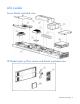
ATA models Server blade exploded view HP BladeSystem p-Class sleeve and blanks exploded view Illustrated parts catalog 6
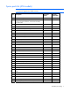
Spare parts list (ATA models) NOTE: Always retain the server blade handle. The handle contains a serial number that maintains the original server blade warranty. Item Description Spare part number Customer replaceable? 381803-001 Yes Processor — — a) 2.4-GHz AMD Opteron™ single-core 381836-001 Yes b) 1.8-GHz AMD Opteron™ dual-core 395083-001 Yes c) 2.0-GHz AMD Opteron™ dual-core 395084-001 Yes d) 2.2-GHz AMD Opteron™ dual-core 395085-001 Yes e) 2.
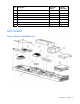
Item Description Spare part number Customer replaceable? 12 HP BladeSystem p-Class sleeve board 361746-001 Yes 13 Air baffle (dual-core processor systems only) 398028-001 Yes 14 Cable kit * 381805-001 Yes a) Power button/LED cable — — b) Hard drive cable — — 15 Replacement battery, 3-V lithium * 234556-001 Yes 16 Local I/O cable * 355935-001 Yes *Not shown SAS models Server blade exploded view Illustrated parts catalog 8
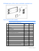
HP BladeSystem p-Class sleeve and blanks exploded view Spare parts list (SAS models) NOTE: Always retain the server blade handle. The handle contains a serial number that maintains the original server blade warranty. Item Description Spare part number Customer replaceable? 404677-001 Yes Processor — — a) 1.8-GHz AMD Opteron™ dual-core 395083-001 Yes b) 2.2-GHz AMD Opteron™ dual-core 395085-001 Yes c) 2.
Item Description Spare part number Customer replaceable? 7 Heatsink, dual-core processor 396768-001 Yes 8 SAS controller 403624-001 Yes 9 Hard drives — — a) 36-GB SAS 404784-001 Yes b) 72-GB SAS 404785-001 Yes c) 146-GB SAS 437862-001 Yes Hardware kit 404678-001 Yes a) 3U server blade blank — — b) Drive cage assembly * — — c) Latch release, spring, and screw * — — 11 HP BladeSystem p-Class sleeve access panel 361881-001 Yes 12 HP BladeSystem p-Class sleeve board 36
Removal and replacement procedures In this section Safety considerations.............................................................................................................................. 11 Preparation procedures........................................................................................................................... 12 ATA drive cage assembly........................................................................................................................
Rack warnings and cautions WARNING: To reduce the risk of personal injury or damage to the equipment, be sure that: • The leveling jacks are extended to the floor. • The full weight of the rack rests on the leveling jacks. • The stabilizing feet are attached to the rack if it is a single-rack installation. • The racks are coupled together in multiple-rack installations. • Only one component is extended at a time. A rack may become unstable if more than one component is extended for any reason.
Power down the server blade Before powering down the server blade, always back up critical data. Power down the server blade using either of the following methods: • Press the Power On/Standby button on the server blade front panel. Be sure that the server blade is in standby mode by observing that the power LED is amber. This process may take 30 seconds, during which time some internal circuitry remains active. • Use the virtual power button feature in iLO.
ATA drive cage assembly To remove the component: 1. Power down the server blade (on page 13). 2. Remove the server blade (on page 13). 3. Remove the drive cage assembly. IMPORTANT: Be sure to disconnect the hard drive cable from the system board before removing the drive cage assembly. To replace the component, reverse the removal procedure. ATA hard drive option To remove the component: 1. Power down the server blade (on page 13). 2. Remove the server blade (on page 13). 3.
4. Remove the cover plate and, if necessary, the center plate. 5. Remove the drive from the cage. To replace the component, reverse the removal procedure. The drive cage assembly lower drive bay is designated as the primary hard drive bay and must be populated first. Before installing a hard drive, be sure the jumper on the hard drive is set to CS so that the drive device ID is determined by the hard drive connection to the hard drive cable. SAS drive cage assembly To remove the component: 1.
3. Remove the drive cage assembly. To replace the component, reverse the removal procedure. SAS hard drive option To remove the component: 1. Power down the server blade (on page 13). 2. Remove the server blade (on page 13). 3. Remove the SAS drive cage assembly (on page 15). 4. Remove the cover plate and, if necessary, the center plate.
5. Remove the hard drive. To replace the component, reverse the removal procedure. The drive cage assembly lower drive bay is designated as the primary hard drive bay and must be populated first. SAS controller and cables To remove the component: 1. Power down the server blade (on page 13). 2. Remove the server blade (on page 13). 3. Disconnect the hard drive cables from the hard drives.
4. Disconnect the cables from the controller. 5. Remove the SAS controller. To replace the component, reverse the removal procedure. Air baffle (dual-core processor models only) To remove the component: 1. Power down the server blade (on page 13). 2. Remove the server blade (on page 13).
3. Remove the air baffle. CAUTION: To ensure proper airflow, always install the air baffle when installing a dual-core processor. To replace the component, reverse the removal procedure. DIMMs To remove the component: 1. Power down the server blade (on page 13). 2. Remove the server blade (on page 13). 3. For DIMM bank B, remove the air baffle. ("Air baffle (dual-core processor models only)" on page 18) NOTE: Dual-core processor models only.
4. Remove the DIMM. To replace the component, reverse the removal procedure. CAUTION: Use only HP DIMMs. DIMMs from other sources may adversely affect data integrity. Observe the following DIMM installation guidelines: • All DIMMs must be PC3200 DDR 400-MHz SDRAM DIMMs, or PC2700 DDR 333-MHz SDRAM DIMMs. • Both DIMM slots in a bank must be populated. • Both DIMMs in a bank must be identical. • DIMM bank A must always be populated.
3. Open the processor cage and remove the heatsink. IMPORTANT: Processor socket 1 must always be populated. If processor socket 1 is empty, the server blade does not power up. 4. Remove the processor. To replace the component: 1. Install the processor. CAUTION: Be sure that the processor socket locking lever is open before installing the processor into the socket. CAUTION: The processor is designed to fit one way into the socket.
CAUTION: Be sure that the processor socket locking lever is closed after the processor is installed. The lever should close without resistance. Forcing the lever closed can damage the processor and socket, requiring system board replacement. 2. Close the processor locking lever. 3. Remove the protective cover from the thermal interface.
4. Insert the heatsink and close the processor cage. Closing the processor cage aligns the heatsink. CAUTION: To ensure proper cooling of the dual-core processor, the old air baffle must be replaced when upgrading from a single-core processor to a dual-core processor. IMPORTANT: To ensure proper cooling, be sure the correct processor air baffle is installed at all times. Fan assembly To remove the component: 1. Power down the server blade (on page 13). 2. Remove the server blade (on page 13). 3.
5. Remove the fan assembly. To replace the component, reverse the removal procedure. Dual Port Fibre Channel Adapter (2 GB) To remove the component: 1. Power down the server blade (on page 13). 2. Remove the server blade (on page 13). 3. Remove the FC adapter. To replace the component, reverse the removal procedure. NIC riser board To remove the component: 1. Power down the server blade (on page 13).
2. Remove the server blade (on page 13). 3. Remove the Dual Port Fibre Channel Adapter, if installed ("Dual Port Fibre Channel Adapter (2 GB)" on page 24). 4. Remove the NIC riser board. To replace the component, reverse the removal procedure. Power converter module To remove the component: 1. Power down the server blade (on page 13). 2. Remove the server blade (on page 13). 3. Remove the power converter module.
To replace the component, reverse the removal procedure. Power button/LED cable To remove the component: 1. Power down the server blade (on page 13). 2. Remove the server blade (on page 13). 3. Remove the drive cage assembly ("ATA drive cage assembly" on page 14, "SAS drive cage assembly" on page 15). 4. Remove the air baffle, if necessary ("Air baffle (dual-core processor models only)" on page 18). 5. Remove the fan assembly ("Fan assembly" on page 23). 6. Remove the power button/LED cable.
3. Remove the server blade handle. To replace the component: 1. Place the server blade handle over the spring on the server blade. 2. Install the screw to secure the handle and spring. System board assembly The system board assembly consists of the system board, the chassis, the power button/LED board, and the two cables. To remove the component: 1. Power down the server blade (on page 13). 2. Remove the server blade (on page 13). 3.
Server blade blanks CAUTION: To prevent improper cooling and thermal damage, do not operate the server blade enclosure unless all bays are populated with either a component or a blank. To remove the 6U server blade blank: To remove the 3U server blade blank: HP BladeSystem p-Class sleeve To remove the component: 1. Power down the server blade (on page 13). 2. Remove the server blade (on page 13). 3. Remove the second server blade, if installed. 4.
5. Remove the HP BladeSystem p-Class sleeve. To replace the component, reverse the removal procedure. HP BladeSystem p-Class sleeve board To remove the component: 1. Remove the HP BladeSystem p-Class sleeve ("HP BladeSystem p-Class sleeve" on page 28). 2. Remove the HP BladeSystem p-Class sleeve access panel.
3. Remove the HP BladeSystem p-Class sleeve board. To replace the component, reverse the removal procedure.
Diagnostic tools In this section Troubleshooting resources ....................................................................................................................... 31 HP Insight Diagnostics............................................................................................................................. 31 Survey Utility..........................................................................................................................................
This utility supports operating systems that may not be supported by the server blade. For operating systems supported by the server blade, refer to the HP website (http://www.hp.com/go/supportos). If a significant change occurs between data-gathering intervals, the Survey Utility marks the previous information and overwrites the Survey text files to reflect the latest changes in the configuration.
and remotely through ISEE for OpenVMS, Tru64, and Microsoft® Windows® operating system binary error logs. For more information, refer to the HP website (http://h18000.www1.hp.com/support/svctools/). Open Services Event Manager OSEM is a standalone tool that performs real-time reactive and proactive service event filtering, analysis, and notification. The tool gathers event data from SNMP traps or information provided over an HTTP interface and notifies an administrator or HP through SMTP and ISEE.
Component identification In this section Server blade components ........................................................................................................................ 34 Sleeve board and server blade LED locations ............................................................................................ 37 Local I/O cable .....................................................................................................................................
Item Description Status 4 NIC 2 LED* Green = Network linked Green flashing = Network activity Off = No link or activity 5 Hard drive activity LED Green/Flashing = Activity Off = No activity 6 Power On/Standby button LED Green = On Amber = Standby (auxiliary power available) Off = Off 7 Local I/O port** — * Actual NIC numeration depends on several factors, including the operating system installed on the server blade.
Internal components Item Description 1 Fan assembly connectors (2) 2 Processor socket 2 3 DIMM bank A (populated) 4 Adapter card connectors (2) 5 Battery 6 Processor socket 1 (populated) 7 DIMM bank B 8 Hard drive cable connector 9 System maintenance switch (SW1) 10 Fan assembly 11 Hard drive cage Component identification 36
System maintenance switch Position Default Function S1 Off Off = iLO security is enabled. On = iLO security is disabled. S2 Off Off = System configuration can be changed. On = System configuration is locked. S3 Off Reserved S4 Off Reserved S5 Off Off = Power-on password is enabled. On = Power-on password is disabled.
Local I/O cable Item Connector Description 1 Local I/O For connecting to the local I/O port on the server blade front panel 2 Video For connecting a video monitor 3 USB 1 For connecting a USB device 4 USB 2 For connecting a USB device 5 Serial For trained personnel to connect a null-modem serial cable and perform advanced diagnostic procedures 6 iLO RJ-45 (10/100 Ethernet) For connecting an Ethernet to the server blade iLO interface from a client device Server blade enclosure bay numbe
Server blade enclosure compatibility The HP ProLiant BL35p Server Blades require the support of an HP BladeSystem p-Class sleeve in a server blade enclosure with enhanced backplane components (enhanced server blade enclosure). The enhanced server blade enclosure also provides a single rear iLO connector for single-cable remote management of all installed HP ProLiant BL35p Server Blades.
Specifications In this section Environmental specifications .................................................................................................................... 40 Server blade specifications......................................................................................................................
Acronyms and abbreviations DDR double data rate ESD electrostatic discharge FC Fibre Channel I/O input/output iLO Integrated Lights-Out IML Integrated Management Log IP Internet Protocol ISEE Instant Support Enterprise Edition LED light-emitting diode NIC network interface controller OSEM Open Services Event Manager POST Power-On Self Test Acronyms and abbreviations 41
PSP ProLiant Support Pack RBSU ROM-Based Setup Utility RILOE Remote Insight Lights-Out Edition ROM read-only memory SFP small form-factor pluggable SIM Systems Insight Manager SNMP Simple Network Management Protocol UID unit identification WEBES Web-Based Enterprise Service Acronyms and abbreviations 42
Index A adapters 36 air baffle 18 ATA hard drives 14 B board components 36 buttons 34 C cable connector identification 38 cables 38 cabling 38 cautions 12 component identification 34, 36, 37 connectors 34, 36, 38 CSR (customer self repair) 5 customer self repair (CSR) 5 D default settings 37 diagnostic tools 31 diagnostics utility 31 DIMM installation guidelines 19 DIMM slots 36 DIMMs 19 drive cage assembly, ATA 14 drive cage assembly, SAS 15 Dual Port FC Adapter 24 E electrostatic discharge 11 environm
R rack warnings 12 remote support and analysis tools 32, 33 removal and replacement procedures 11 removing server from rack 13 removing the server blade 13 S safety considerations 11 SAS connector 17 SAS drives 16 SAS hard drive cabling 17 serial port 38 server blade bay blank 28 server blade enclosure 39 sleeve, HP BladeSystem p-Class 28, 37 specifications 40 specifications, environmental 40 Standby mode, entering 13 static electricity 11 Survey Utility 31 system board 27 system board components 36 system