HP ProLiant BL40p Server Blade Maintenance and Service Guide June 2003 (Second Edition) Part Number 316079-002
© 2003 Hewlett-Packard Development Company, L.P. Microsoft and Windows are U.S. registered trademarks of Microsoft Corporation. Intel is a registered trademark of Intel Corporation in the US and other countries and is used under license. Hewlett-Packard Company shall not be liable for technical or editorial errors or omissions contained herein. The information in this document is provided “as is” without warranty of any kind and is subject to change without notice.
Contents About This Guide Audience Assumptions............................................................................................................................... vii Technician Notes........................................................................................................................................ vii Where to Go for Additional Help.............................................................................................................. viii Integrated Management Log ...
Contents Battery ...............................................................................................................................................2-34 System Board ....................................................................................................................................2-36 Server Blade Blanks ..........................................................................................................................
Contents 2-18 2-19 2-20 2-21 2-22 2-23 2-24 2-25 2-26 2-27 2-28 2-29 2-30 2-31 2-32 2-33 2-34 2-35 2-36 2-37 4-1 4-2 4-3 4-4 4-5 4-6 5-1 5-2 5-3 Removing a power module ............................................................................................................... 2-19 Removing the processor baffle ......................................................................................................... 2-20 Removing the processor cage .......................................................
About This Guide This maintenance and service guide can be used for reference when servicing ProLiant BL40p server blades. WARNING: To reduce the risk of personal injury from electric shock and hazardous energy levels, only authorized service technicians should attempt to repair this equipment. Improper repairs can create conditions that are hazardous. Audience Assumptions This guide is for service technicians.
About This Guide CAUTION: To properly ventilate the system, you must provide at least 7.6 cm (3.0 in) of clearance at the front and back of the server. CAUTION: The computer is designed to be electrically grounded (earthed). To ensure proper operation, plug the AC power cord into a properly grounded AC outlet only. NOTE: Any indications of component replacement or printed wiring board modifications may void any warranty.
About This Guide Telephone Numbers For the name of the nearest HP authorized reseller: • In the United States, call 1-800-345-1518. • In Canada, call 1-800-263-5868. For HP technical support: • In the United States and Canada, call 1-800-652-6672. • Outside the United States and Canada, refer to www.hp.
1 Illustrated Parts Catalog This chapter provides illustrated parts and spare parts lists for the HP ProLiant BL40p server blade components. Table 1-1 lists the referenced spare parts.
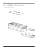
Illustrated Parts Catalog ProLiant BL40p Server Blade Components Mechanical Exploded View Figure 1-1: ProLiant BL40p server blade mechanical components 1-2 HP ProLiant BL40p Server Blade Maintenance and Service Guide
Illustrated Parts Catalog System Exploded View Figure 1-2: ProLiant BL40p server blade system components HP ProLiant BL40p Server Blade Maintenance and Service Guide 1-3
Illustrated Parts Catalog Server Blade Spare Parts List Table 1-1: Server Blade Spare Parts List Item Description Spare Part Number Mechanical Components 1 Access panel 314456-001 2 Hard drive blank 122759-001 Boards 3 Front panel power button/LED board 303478-001 4 SCSI backplane board 303474-001 5 System board 303475-001 6 PCI-X mezzanine board 303477-001 7 HP Smart Array 5i Controller module 260741-001 8 NIC I/O board 303473-001 9 Ethernet passthrough board 303476-001 Syste
Illustrated Parts Catalog Table 1-1: Server Blade Spare Parts List continued Item Description 16e Processor baffle cover 16f LED power switch bezel * 16g Drive cage bezel * 16h Mate left bezel * 16i Mate upper right bezel * 16j Mate lower right bezel * 16k SCSI fan latch, left * 16l System board tray assembly ejector lever * 16m Battery carrier * Spare Part Number 17 Fans 314453-001 18 Cable kit * 314454-001 18a RJ-45 signal board * 18b Power button/LED board * 18c Processor
Illustrated Parts Catalog Table 1-1: Server Blade Spare Parts List continued Item Description Spare Part Number Memory 22 DIMM, 256-MB, registered, PC2100 ECC DDR 300699-001 23 DIMM, 512-MB, registered, PC2100 ECC DDR * 300700-001 24 DIMM, 1-GB, registered, PC2100 ECC DDR * 300701-001 25 DIMM, 2-GB, registered, PC2100 ECC DDR * 300702-001 Options 26 Battery-Backed Write Cache Enabler, with cable 260740-001 * Not shown 1-6 HP ProLiant BL40p Server Blade Maintenance and Service Guide
2 Removal and Replacement Procedures This chapter provides subassembly/module-level removal and replacement procedures for system components. After completing all necessary removal and replacement procedures, verify that all components operate properly by running the appropriate diagnostic software: • For server blade components, run the Server Diagnostics utility, available from the HP website: www.hp.com • For server blade enclosure and power enclosure components, run the infrastructure diagnostics.
Removal and Replacement Procedures WARNING: Setting the server blade Power On/Standby button to the standby position removes power from most areas of the server blade. This process may take 30 seconds, during which time some internal circuitry remains active. To remove power completely, remove the server blade from the server blade enclosure. WARNING: To reduce the risk of personal injury from hot surfaces, allow the internal system components to cool before touching them.
Removal and Replacement Procedures WARNING: To reduce the risk of shock or injury from high current electrical energy, do not reach into a server blade enclosure once it has been installed in a rack and connected to a working rack bus bar. Do not touch the power or data backplanes within the server blade enclosure once it has been installed.
Removal and Replacement Procedures Server Blade Components Use the procedures in this section to perform service events on ProLiant BL40p server blades. NOTE: Slate blue components denote serviceable parts. Server Blade Preparation To service any internal server blade component, you must power down the server blade and remove it from the server blade enclosure. CAUTION: Electrostatic discharge can damage electronic components. Be sure you are properly grounded before beginning any installation procedure.
Removal and Replacement Procedures Figure 2-1: Pressing the Power On/Standby button CAUTION: After you press the release button, the server blade is unlocked from the server blade enclosure. Use both hands to support the server blade when you remove it from the rack. 3. Remove the server blade from the server blade enclosure: a.
Removal and Replacement Procedures Figure 2-2: Unlocking the server blade from the server blade enclosure b. Press the button to release the locking lever (1). c. Pull open the locking lever (2). d. Grasp the lever and slide the server blade from the server blade enclosure (3). Place a hand under the server blade to support it as you remove it from the enclosure. Figure 2-3: Removing the server blade from the server blade enclosure 4. Place the server blade on a flat, level surface.
Removal and Replacement Procedures CAUTION: Always populate server blade enclosure bays with either a server blade or server blade blank. Operating the server blade enclosure without a server blade or server blade blank results in improper airflow and improper cooling that can lead to thermal damage. Reverse steps 1 through 3 to install and power up a server blade. Server blades are set to power up automatically upon insertion.
Removal and Replacement Procedures Access Panel To remove the access panel: 1. Power down the server blade and remove it from the server blade enclosure. Refer to the “Server Blade Preparation” section in this chapter. 2. Lift up on the hood latch handle until the access panel disengages from the chassis (1). 3. Slide the access panel about 1.3 cm (0.5 in) toward the rear of the unit and lift the panel to remove it (2).
Removal and Replacement Procedures Removing the System Board Tray Assembly The system board tray assembly must be removed from the chassis for the replacement of some components, but is not required for all preparation procedures. Refer to the instructions for replacing a specific option to determine whether the system board tray must be removed. Refer to Figure 2-6 for connector locations on the system board.
Removal and Replacement Procedures 3. Remove the three-fan assembly: a. Disconnect the fan cable from the PCI-X mezzanine board (1). b. Pull out the slate blue fan clips located underneath the assembly (2). c. Lift the assembly out of the chassis (3). Figure 2-7: Removing the three-fan assembly 4. Remove the DC power converter from the system board. Refer to the label on the DC power converter for details. 5. Disconnect the RJ-45 cables from the PCI-X mezzanine board.
Removal and Replacement Procedures 6. Carefully disconnect the SCSI I2C cable and the SCSI backplane power cable from the SCSI backplane board: a. Open the chassis doors on either side of the SCSI backplane board for easier access to the cables. Refer to Figure 2-31 for details. b. Pinch the cable clips, and pull the cables out of the connectors. CAUTION: The SCSI I2C cable and the SCSI backplane power cable must remain attached to the system board at this point.
Removal and Replacement Procedures 7. Secure the SCSI I2C cable and the SCSI backplane power cable into the processor baffle. NOTE: Figure 2-9 shows the system board tray assembly removed from the chassis for clarity. Figure 2-9: Attaching cables to the processor baffle 8. Disconnect both SCSI cables from the SCSI backplane board (1, 4) and from the system board (2, 3). NOTE: Numbers 3 and 4 in Figure 2-10 reference ports A (short cable). Numbers 1 and 2 reference ports B (long cable).
Removal and Replacement Procedures 9. Lift the system board tray release latch (1) and turn a quarter turn to unlock the system board tray from the chassis (2). 10. Push the plastic hook to release the slate blue system board tray lever (3) and slowly pull it forward to slide the tray towards the front of the server blade (4). IMPORTANT: To avoid damaging the equipment, be sure to lift all cables away from the system board before sliding the tray out. Figure 2-11: Unlocking the system board tray 11.
Removal and Replacement Procedures Host-Bus Adapter Cards The ProLiant BL40p server blade PCI-X expansion slots support only fibre channel host-bus adapter cards. To install a host-bus adapter card into a PCI-X slot: 1. Power down the server blade and remove it from the server blade enclosure. Refer to “Server Blade Preparation” in this chapter. 2. Remove the access panel. Refer to “Access Panel” in this chapter. 3.
Removal and Replacement Procedures 5. Open the slate blue alignment guide (1). 6. Install the host-bus adapter card into PCI-X slot 1 (2). 7. Close the slate blue alignment guide (3) 8. Close the release lever (4). Figure 2-14: Installing a host-bus adapter card 9. Repeat steps 2 through 6 for PCI-X slot 2 if installing an additional host-bus adapter card. 10. Reinstall the access panel. 11. Install the server blade into the server blade enclosure. 12. Cable the host-bus adapter card as necessary.
Removal and Replacement Procedures Hard Drive Blanks To remove a hard drive blank: 1. Press the release buttons simultaneously (1). 2. Pull the blank out of the drive bay (2). Figure 2-15: Removing a hard drive blank CAUTION: Always populate hard drive bays with either a hot-plug SCSI hard drive or hard drive blank. Operating the server blade without a hot-plug SCSI hard drive or hard drive blank results in improper airflow and improper cooling that can lead to thermal damage.
Removal and Replacement Procedures Hot-Plug SCSI Hard Drives To assess hard drive status, observe the hot-plug SCSI hard drive status LEDs. For a detailed explanation of these LEDs, refer to Chapter 4, “Connectors, LEDs, and Switches.” CAUTION: Read the section on hot-plug hard drive replacement in the HP Servers Troubleshooting Guide before removing a hard drive. IMPORTANT: It is not necessary to power down the server blade before removing or replacing a hot-plug SCSI hard drive.
Removal and Replacement Procedures DIMMs To remove a DIMM: 1. Power down the server blade and remove it from the server blade enclosure. Refer to the “Server Blade Preparation” section in this chapter. 2. Remove the access panel. Refer to the “Access Panel” section in this chapter. NOTE: The server blade ships with at least two DIMMs installed in slots 1A and 2A. 3. Open the DIMM slot latches (1). 4. Remove the DIMM from the slot (2).
Removal and Replacement Procedures Power Modules The ProLiant BL40p server blade has two system board power modules and one PCI-X mezzanine power module. Refer to Figure 4-3 and Table 4-2 for locations. To remove a power module: 1. Power down the server blade and remove it from the server blade enclosure. Refer to the “Server Blade Preparation” section in this chapter. 2. Remove the access panel. Refer to the “Access Panel” section in this chapter. 3.
Removal and Replacement Procedures Processors The ProLiant BL40p server blade has the capability of up to four Xeon processors. To remove a processor: 1. Power down the server blade and remove it from the server blade enclosure. Refer to “Server Blade Preparation” in this chapter. 2. Remove the access panel and the system board tray assembly. Refer to “Server Blade Preparation” in this chapter. 3. Slide the processor baffle back and lift it off of the processor assemblies.
Removal and Replacement Procedures 4. Lift the slate blue processor cage lever to release the processor cage (1). 5. Raise the processor cage away from the processor assembly (2). Figure 2-20: Removing the processor cage 6. Lift the processor-locking lever to release the processor assembly (1). 7. Lift the processor assembly away from the processor socket (2).
Removal and Replacement Procedures CAUTION: To avoid damage to the processors and processor sockets, be sure to: • Completely open the processor-locking lever when installing a processor assembly. • Completely close the processor-locking lever before lowering the processor cage. To install the processor, reverse steps 1 through 7. Be sure to correctly align the pins when lowering the processor assembly onto the socket. Processor Power Module To remove a PPM: 1.
Removal and Replacement Procedures DC Power Converter Refer to the label on the DC power converter for removal instructions. Smart Array 5i Plus Memory Module To remove the Smart Array 5i Plus memory module: 1. Power down the server blade and remove it from the server blade enclosure. Refer to the “Server Blade Preparation” section in this chapter. 2. Remove the access panel. Refer to the “Access Panel” section in this chapter. 3. Remove the DC power converter from the system board.
Removal and Replacement Procedures Battery-Backed Write Cache Enabler To remove the Smart Array 5i Battery-Backed Write Cache Enabler: 1. Power down the server blade and remove it from the server blade enclosure. Refer to the “Server Blade Preparation” section in this chapter. 2. Remove the access panel. Refer to the “Access Panel” section in this chapter. 3. Remove the DC power converter from the system board. Refer to the label on the DC power converter. 4.
Removal and Replacement Procedures 5. Turn the standoffs to release the Battery-Backed Write Cache Enabler (1), and lift it off of the system board (2). Figure 2-25: Removing the Battery-Backed Write Cache Enabler Reverse steps 1 through 5 to replace the Battery-Backed Write Cache Enabler.
Removal and Replacement Procedures Processor Fan Assembly To remove the processor fan assembly: 1. Power down the server blade and remove it from the server blade enclosure. Refer to the “Server Blade Preparation” section in this chapter. 2. Remove the access panel. Refer to the “Access Panel” section in this chapter. 3. Remove the system board tray assembly. Refer to the “Removing the System Board Tray Assembly” section in this chapter. 4. Disconnect the fan cable from the system board.
Removal and Replacement Procedures 6. Press in the spring locks on either side of the fan assembly (1), and slide the fan assembly out (2). 7. To remove an individual fan, squeeze the port-colored levers on either side of the fan (3), and lift the fan out (4). Figure 2-27: Removing the processor fan assembly Reverse steps 1 through 6 to replace the processor fan assembly.
Removal and Replacement Procedures Ethernet Passthrough Board To remove the Ethernet passthrough board: 1. Power down the server blade and remove it from the server blade enclosure. Refer to the “Server Blade Preparation” section in this chapter. 2. Remove the access panel. Refer to the “Access Panel” section in this chapter. 3. Disconnect RJ-45 cables from either the PCI-X mezzanine board or the Ethernet passthrough board. 4.
Removal and Replacement Procedures PCI-X Mezzanine Board To remove the PCI-X mezzanine board: 1. Power down the server blade and remove it from the server blade enclosure. Refer to “Server Blade Preparation” in this chapter. 2. Remove the access panel and the system board tray assembly. Refer to “Server Blade Preparation” in this chapter. 3. Disconnect RJ-45 cables from the PCI-X mezzanine board. 4. Remove any host-bus adapter cards installed in the PCI-X mezzanine board.
Removal and Replacement Procedures NIC I/O Board To remove the NIC I/O board: 1. Power down the server blade and remove it from the server blade enclosure. Refer to the “Server Blade Preparation” section in this chapter. 2. Remove the access panel and the system board tray assembly. Refer to the “Server Blade Preparation” section in this chapter. 3. Remove the PCI-X mezzanine board. Refer to the “PCI-X Mezzanine Board” section in this chapter. 4.
Removal and Replacement Procedures SCSI Backplane To remove the SCSI backplane: 1. Power down the server blade and remove it from the server blade enclosure. Refer to the “Server Blade Preparation” section in this chapter. 2. Remove the access panel. Refer to the “Access Panel” section in this chapter. 3. Remove any hot-plug SCSI hard drives or hard drive blanks: — If any hard drive blanks are installed, refer to the “Hard Drive Blanks” section in this chapter.
Removal and Replacement Procedures 7. Turn the thumbscrew to release the SCSI backplane (1) and lift out (2). Figure 2-32: Removing the SCSI backplane Reverse steps 1 through 7 to replace the SCSI backplane.
Removal and Replacement Procedures Power Button/LED Board To remove the power button/LED board: 1. Power down the server blade and remove it from the server blade enclosure. Refer to the “Server Blade Preparation” section in this chapter. 2. Remove the access panel and the system board tray assembly. Refer to the “Server Blade Preparation” section in this chapter. 3. Use a Torx-15 screwdriver to remove the two retaining screws from the power button/LED board (1). 4.
Removal and Replacement Procedures Battery If the server blade no longer automatically displays the correct date and time, you may need to replace the battery that provides power to the real-time clock. Under normal use, battery life is 5 to 10 years. WARNING: This server blade contains either an internal lithium manganese dioxide or a vanadium pentoxide battery. A risk of fire and burns exists if the battery pack is not handled properly.
Removal and Replacement Procedures 4. Insert a pen or other narrow object into the slot at the front of the battery holder to release the battery (1). 5. Lift the battery away from the battery holder (2). Figure 2-34: Removing the battery from the system board Reverse steps 1 through 5 to replace the system board battery.
Removal and Replacement Procedures System Board To remove the system board: 1. Power down the server blade and remove it from the server blade enclosure. Refer to the “Server Blade Preparation” section in this chapter. 2. Remove the access panel and the system board tray assembly. Refer to the “Server Blade Preparation” section in this chapter. 3. Remove the DIMMs. Refer to the “DIMMs” section in this chapter. 4. Remove the PPMs. Refer to the “Processor Power Module” section in this chapter. 5.
Removal and Replacement Procedures 12. Slide the system board toward the front of the server blade (1). Be sure that the board unseats from the alignment keys. 13. Using the handles on the processor cages and the PCI-X support handle, lift the system board out of the chassis (2). Figure 2-36: Disengaging the system board Reverse steps 1 through 13 to replace the system board.
Removal and Replacement Procedures Server Blade Blanks To remove a server blade blank: 1. Press the release buttons simultaneously (1). 2. Slide the server blade blank from the server blade enclosure (2). Figure 2-37: Removing a server blade blank CAUTION: Always populate server blade enclosure bays with either a server blade or server blade blank.
3 Diagnostic Tools This chapter is an overview of software and firmware diagnostic tools that are available for configuring, monitoring, and managing the system. Refer to the HP ProLiant BL40p Server Blade Setup and Installation Guide on the Documentation CD, or to www.hp.
Diagnostic Tools ProLiant BL p-Class Diagnostic Tools Use the following tools to diagnose problems, test hardware, and monitor and manage system operations. Table 3-1: Diagnostic Tools Tool Description How to run the tool Array Diagnostics Utility (ADU) ADU is designed to run on all HP systems that support HP array controllers. ADU collects information about the array controllers in the system and generates a list of detected problems.
Diagnostic Tools Table 3-1: Diagnostic Tools continued Tool Description How to run the tool Survey Utility The Survey Utility gathers critical hardware and software information on server blades. The Survey Utility is available on the ProLiant Essential Rapid Deployment Pack CD or on the HP website: If a significant change occurs between data-gathering intervals, the Survey Utility marks the previous information and overwrites the survey text files to reflect the latest changes in the configuration.
Diagnostic Tools Table 3-1: Diagnostic Tools continued Tool Description How to run the tool Nteventlog file The nteventlog file implies a Microsoft Windows OS and records server blade activity. View the nteventlog file through the Windows Event Viewer. ROM-Based Setup Utility (RBSU) RBSU configures the hardware installed in the server blade. This utility enables users to: Run RBSU by pressing the F9 key during POST. • Store configuration information in nonvolatile memory.
4 Connectors, LEDs, and Switches This chapter explains the location and function of system connectors, internal and external LEDs, and switches.
Connectors, LEDs, and Switches Connectors Use the following sections to identify connectors on the ProLiant BL40p server blade. Front Panel Connectors The server blade has one front panel connector, a diagnostic port that accepts the diagnostic cable for configuration and troubleshooting purposes.
Connectors, LEDs, and Switches Rear Panel Connectors Use Figure 4-2 and Table 4-1 to identify ProLiant BL40p server blade rear panel connectors. Figure 4-2: ProLiant BL40p server blade rear panel connectors Table 4-1: ProLiant BL40p Server Blade Rear Panel Connectors Item Description 1 Power connectors 2 Signal connectors System Components and Connectors Use Figure 4-3 and Table 4-2 to identify ProLiant BL40p system components and connectors.
Connectors, LEDs, and Switches Figure 4-3: ProLiant BL40p system components and connectors Table 4-2: System Components and Connectors Item Component Item Component 1 Processor socket 3 18 Smart Array 5i Plus memory module 2 LED/power switch board connector 19 System board 3 PPM slot 3 20 DC power converter connector 4 SCSI I2C cable connector 21 DIMM slots (6) 5 PPM slot 4 22 System board power modules (2)* 6 Processor socket 4 23 Channel B SCSI connector 7 System battery 24
Connectors, LEDs, and Switches LEDs Use the following section to identify LEDs on the following ProLiant BL p-Class system components: • ProLiant BL40p server blade front panel • Hot-plug SCSI hard drives ProLiant BL40p Server Blade Front Panel Six LEDs on the front of the server blade indicate server status. Use Figure 4-4 and Table 4-3 to identify LED locations and functions.
Connectors, LEDs, and Switches Table 4-3: ProLiant BL40p Server Blade Front Panel LEDs continued Item 3 LED Description Status External health Green = Normal (when server blade is powered on) Off = Normal (when server blade is on standby) Amber = Redundant fan failed Red = Critical fan failure 4 NIC 1 Green = Linked to network 5 NIC 2 Green flashing = Network activity 6 NIC 3 Off = No activity 7 NIC 4 8 NIC 5 9 Power On/Standby Green = On Amber = Standby (power available) Off = Unit off
Connectors, LEDs, and Switches Table 4-4: Hot-Plug SCSI Hard Drive LEDs 1 Activity 2 Online 3 Fault Means On Off Off Do not remove the drive. Removing a drive during this process causes data loss. The drive is being accessed and is not configured as part of an array. On Flashing Off Do not remove the drive. Removing a drive during this process causes data loss. The drive is rebuilding or undergoing capacity expansion. Flashing Flashing Flashing Do not remove the drive.
Connectors, LEDs, and Switches Switches Use the following sections to identify the locations and functions of push-button and system switches. System Switches System switches enable you to change certain settings or to perform advanced diagnostic procedures. The following sections explain the functions of each switch. Use Figure 4-6 and Table 4-5 to identify switch locations and functions.
Connectors, LEDs, and Switches System ID Switch (SW1) The system ID switch is a three-position switch used for chassis ID. Settings should be changed only by an authorized service provider. Refer to Table 4-6 for system ID switch settings. Table 4-6: System ID Switch (SW1) Settings Position Description On/Off Function 1 Chassis ID0 2 Chassis ID1 All pins will be set to off. HP does not recommend changing this switch setting.
5 Port 84 Codes Determining Port 84 Codes A combination of port 84 LEDs is translated into a hexadecimal code, which can be used for troubleshooting. This chapter describes how to determine the port 84 code, and what the codes mean. Refer to Figure 5-1 for the location of the port 84 LEDs. The port 84 LEDs can be viewed using one of these methods: • With the server blade in the enclosure, log into iLO to view the port 84 codes.
Port 84 Codes Figure 5-1: Port 84 location on the system board 5-2 HP ProLiant BL40p Server Blade Maintenance and Service Guide
Port 84 Codes The port 84 LEDs consist of two groups of four LEDs. Each group of four LEDs represents one character of the code. Figure 5-2 and Table 5-1 explain the components of the port 84 LEDs. Figure 5-2: Port 84 LEDs Table 5-1: Port 84 LEDs Item Description 1 Front of the server blade* 2 First code character (Most Significant Bit) 3 Second code character (Least Significant Bit) 4 Rear of server blade* * When reading the port 84 LEDs, you must be oriented to the server blade properly.
Port 84 Codes Moving from left to right, the series of numbers assigned to the first four LEDs is translated into a code, which consists of any characters 0 through 9 or A through F. The series of numbers assigned to the next four LEDs is translated into the same code, resulting in a final two-character code. Refer to Table 5-2 to determine how to read the code from the LED pattern.
Port 84 Codes Refer to Figure 5-3 and Table 5-3 for a sample LED reading and the corresponding code determined from that LED reading. Figure 5-3: Sample port 84 reading Table 5-3: Sample Port 84 Code MSB LED LSB LED Status Code 1 Off 0 2 On 1 3 Off 0 4 On 1 5 Off 0 6 On 1 7 On 1 8 Off 0 Using the code translation from Table 5-2, the resulting code would be 56.
Port 84 Codes Defining Port 84 Codes Refer to Table 5-4 for a description of each port 84 code. IMPORTANT: iLO port 84 codes may differ from port 84 LED codes. Table 5-4 defines port 84 codes for the system board port 84 LEDs only.
Port 84 Codes Table 5-4: Port 84 Codes Defined continued Port 84 Code Description 1C Test CMOS 1D Test DMA controller & page registers 1E Test keyboard controller 1F Unused 20 Test real and extended memory 21 Init time-of-day 22 Init 287 coprocessor 23 Test the keyboard and interface 24 Reset A20 and set default CPU speed 25 Test diskette subsystem 26 Test fixed disk subsystem 27 Initialize SCSI drives 28 Perform search for opt & sys ROM 29 Test for valid system configuration
Port 84 Codes Table 5-4: Port 84 Codes Defined continued Port 84 Code Description 3E Unused 3F Unused 40 Start of Base Memory test 41 Check RAM refresh 42 Start write cycle of 128K RAM test 43 Reset parity checks 44 Start verify cycle of 128K RAM test 45 Check for parity errors 46 No RAM errors 47 Got a RAM error 48 Unused 49 Unused 4A Unused 4B Unused 4C Unused 4D Unused 4E Unused 4F Unused 50 CPR test and setup POST 51 Base memory error during CPR reset 52 Start
Port 84 Codes Table 5-4: Port 84 Codes Defined continued Port 84 Code Description 60 Start of memory test 61 Enter protected mode 62 Start memory sizing 63 Get CMOS expected memory size 64 Compare CMOS to detected 65 Start test of extended memory 66 Save size of real and extended memory 67 Update 128K-Option installed CMOS bit 68 Prepare to return to real mode 69 Back in real mode-test successful 6A Back in real mode-error during test 6B Display error messages 6C End of memory te
Port 84 Codes Table 5-4: Port 84 Codes Defined continued Port 84 Code Description 82 Check result from self-test 83 Fail self-test 84 Self-test successful init with 5Dh 85 Unused 86 Start kbd test, reset keyboard 87 Got acknowledge from test 88 Check result of kbd test 89 Test for stuck keys 8A Key seems to be stuck 8B Test keyboard interface 8C Waiting for self-test timeout to fail 8D End of test, no errors 8E Unused 8F Unused 90 Start of CMOS test 91 CMOS seems to be OK
Port 84 Codes Table 5-4: Port 84 Codes Defined continued Port 84 Code Description A4 FDC time-out error A5 FDC failed reset A6 FDC passed reset A7 Unused A8 Start of determine drive type A9 Unused AA Unused AB Unused AC Unused AD Unused AE Unused AF Diskette tests complete B0 Start of fixed drive tests B1 Combo board not found, exit B2 Combo controller failed, exit B3 Testing drive 1 B4 Testing drive 2 B5 Drive error (error condition) B6 Drive failed (failed to respon
Port 84 Codes Table 5-4: Port 84 Codes Defined continued Port 84 Code Description C6 EISA PZ initialization began C7 EISA PZ initialization done C8 Verify Proc config C9 Server Manager/R POST Self Test RMU CA Verify system/board revs CB Unused CC Autoconfigure PCI devices CD Unused CE Unused CF Unused D0 Entry to clear memory routine D1 Ready to go to protected mode D2 Ready to clear extended mem D3 Ready to reset back to real mode D4 Back in real mode/loading IDT D5 Clear
Port 84 Codes Table 5-4: Port 84 Codes Defined continued Port 84 Code Description E8 Unused E9 Unused EA Unused EB Unused EC Unused ED Unused EE Unused EF Unused F0 Unused F1 Unused F2 Unused F3 Unused F4 Unused F5 Unused F6 Unused F7 Unused F8 Unused F9 Unused FA Unused FB Unused FC Unused FD Unused FE Unused FF Unused HP ProLiant BL40p Server Blade Maintenance and Service Guide 5-13
Index A C access panel removing 2-8 replacing 2-8 spare part number 1-4 warning 5-1 ADU See Array Diagnostics Utility (ADU) alignment keys 2-37 Altiris eXpress Deployment Server 3-3 anchor pins, spare part number 1-5 Array Diagnostics Utility (ADU) access 3-2 description 3-2 ASR-2 See Automatic Server Recovery-2 (ASR-2) Automatic Server Recovery-2 (ASR-2) access 3-2 description 3-2 cables and cabling Battery-Backed Write Cache Enabler 2-23, 2-24 disconnecting system board 2-9 fan 2-10 PCI-X host-bus ada
Index guides HP ProLiant BL p-Class System Setup and Installation Guide 3-2 HP Servers Troubleshooting Guide 3-2 H hard drive blank removing 2-16 replacing 2-16 spare part number 1-4 help resources viii host-bus adapter card, installing 2-14 hot surfaces, warnings 2-3 hot-plug SCSI hard drives LEDs 4-6 removing 2-17 replacing 2-17 HP authorized reseller ix HP Diagnostics utility access 3-2 description 3-2 HP ProLiant BL p-Class System Setup and Installation Guide 3-2 HP Servers Troubleshooting Guide 3-2 H
Index processor power module (PPM) removing 2-22 replacing 2-22 spare part number 1-4 ProLiant Essentials Rapid Deployment Pack access 3-3 description 3-3 S R rack cautions 2-2 warnings 2-2 weight 2-2 RBSU See ROM-Based Setup Utility removing access panel 2-8 battery 2-34 Battery-Backed Write Cache Enabler DIMMs 2-18 hard drive blank 2-16 hot-plug SCSI hard drives 2-17 NIC I/O board 2-30 power button/LED board 2-33 PPM 2-22 processor assembly 2-20 SCSI backplane 2-31 server blade blank 2-38 server blades
Index translating port 84 5-3 ROMPaq 3-2 Survey Utility 3-3 syslog file 3-3 U unit identification (UID), LEDs 4-5 utilities Embedded Server Setup 3-3 HP Diagnostics 3-2 Insight Manager 7 3-2 Integrated Lights-Out ROM-Based Setup Utility (iLO RBSU) 3-3 nteventlog file 3-4 Option ROM Configuration for Arrays (ORCA) 3-3 ProLiant Essentials Rapid Deployment Pack 3-3 RBSU 3-4 Index-4 V ventilation clearances viii voltage regulator module See processor power module (PPM) VRM See processor power module (PPM)