HP ProLiant BL420c Gen8 Server Blade Maintenance and Service Guide Abstract This guide describes identification and maintenance procedures, diagnostic tools, specifications and requirements for hardware components and software. This guide is for an experienced service technician. HP assumes you are qualified in the servicing of computer equipment, trained in recognizing hazards in products, and are familiar with weight and stability precautions.
© Copyright 2012, 2014 Hewlett-Packard Development Company, L.P. The information contained herein is subject to change without notice. The only warranties for HP products and services are set forth in the express warranty statements accompanying such products and services. Nothing herein should be construed as constituting an additional warranty. HP shall not be liable for technical or editorial errors or omissions contained herein. Microsoft® and Windows® are U.S.
Contents Customer self repair ...................................................................................................................... 5 Parts only warranty service ......................................................................................................................... 5 Illustrated parts catalog ............................................................................................................... 15 Server blade components ...........................................
HP Insight Diagnostics survey functionality ........................................................................................ 62 Active Health System ............................................................................................................................... 62 Integrated Management Log ..................................................................................................................... 63 USB support .................................................................
Customer self repair HP products are designed with many Customer Self Repair (CSR) parts to minimize repair time and allow for greater flexibility in performing defective parts replacement. If during the diagnosis period HP (or HP service providers or service partners) identifies that the repair can be accomplished by the use of a CSR part, HP will ship that part directly to you for replacement. There are two categories of CSR parts: • Mandatory—Parts for which customer self repair is mandatory.
Obligatoire - Pièces pour lesquelles la réparation par le client est obligatoire. Si vous demandez à HP de remplacer ces pièces, les coûts de déplacement et main d'œuvre du service vous seront facturés. Facultatif - Pièces pour lesquelles la réparation par le client est facultative. Ces pièces sont également conçues pour permettre au client d'effectuer lui-même la réparation.
In base alla disponibilità e alla località geografica, le parti CSR vengono spedite con consegna entro il giorno lavorativo seguente. La consegna nel giorno stesso o entro quattro ore è offerta con un supplemento di costo solo in alcune zone. In caso di necessità si può richiedere l'assistenza telefonica di un addetto del centro di supporto tecnico HP. Nel materiale fornito con una parte di ricambio CSR, HP specifica se il cliente deve restituire dei componenti.
defekte Teil nicht zurückschicken, kann HP Ihnen das Ersatzteil in Rechnung stellen. Im Falle von Customer Self Repair kommt HP für alle Kosten für die Lieferung und Rücksendung auf und bestimmt den Kurier-/Frachtdienst. Weitere Informationen über das HP Customer Self Repair Programm erhalten Sie von Ihrem Servicepartner vor Ort. Informationen über das CSR-Programm in Nordamerika finden Sie auf der HP Website unter (http://www.hp.com/go/selfrepair).
enviara el componente defectuoso requerido, HP podrá cobrarle por el de sustitución. En el caso de todas sustituciones que lleve a cabo el cliente, HP se hará cargo de todos los gastos de envío y devolución de componentes y escogerá la empresa de transporte que se utilice para dicho servicio. Para obtener más información acerca del programa de Reparaciones del propio cliente de HP, póngase en contacto con su proveedor de servicios local.
Neem contact op met een Service Partner voor meer informatie over het Customer Self Repair programma van HP. Informatie over Service Partners vindt u op de HP website (http://www.hp.com/go/selfrepair). Garantieservice "Parts Only" Het is mogelijk dat de HP garantie alleen de garantieservice "Parts Only" omvat. Volgens de bepalingen van de Parts Only garantieservice zal HP kosteloos vervangende onderdelen ter beschikking stellen.
No caso desse serviço, a substituição de peças CSR é obrigatória. Se desejar que a HP substitua essas peças, serão cobradas as despesas de transporte e mão-de-obra do serviço.
Customer self repair 12
Customer self repair 13
Customer self repair 14
Illustrated parts catalog Server blade components Item Description Spare part number Customer self repair (on page 5) Mechanical components 1 Access panel 688795-001 Mandatory1 2 Drive blank 670033-001 Mandatory1 3 Front panel/drive cage assembly 688800-001 Mandatory1 4 DIMM baffles — — a) DIMM baffle, Processor 1 with T-15 Torx screwdriver and DIMM 688797-001 tool b) DIMM baffle, Processor 2* 688796-001 Mandatory1 Mandatory1 5 Heatsink blank 688803-001 Mandatory1 6 Mezzanine ass
Item Description Spare part number Customer self repair (on page 5) System components 8 9 10 Processors — — a) 1.8-GHz Intel Xeon E5-2403 processor** 676949-001 Optional2 b) 1.8-GHz Intel Xeon E5-2403v2 processor* ** 729109-001 Optional2 c) 2.2-GHz Intel Xeon E5-2407 processor* ** 676948-001 Optional2 d) 2.4-GHz Intel Xeon E5-2407v2 processor * ** 729110-001 Optional2 e) 1.9-GHz Intel Xeon E5-2420 processor* ** 676947-001 Optional2 f) 2.
Item 11 Description Spare part number Customer self repair (on page 5) k) 1-TB, SATA, SFF, 7,200-rpm, 6G* 656108-001 Mandatory1 Solid state drives* — — a) 200-GB, SAS, SLC, SFF, 6G 653961-001 Mandatory1 b) 200-GB, SAS, MLC, SFF, 6G 658580-001 Mandatory1 c) 400-GB, SAS, SLC, SFF, 6G 653962-001 Mandatory1 d) 400-GB, SAS, MLC, SFF, 6G 653963-001 Mandatory1 e) 800-GB, SAS, MLC, SFF, 6G 653964-001 Mandatory1 f) 400-GB, SATA, MLC, SFF, 3G 653967-001 Mandatory1 g) 200-GB, SATA, MLC, SF
Item Description Spare part number Customer self repair (on page 5) b) Cache module, 512-MB 678326-001 Mandatory1 c) HP Smart Array P220i Controller* 670026-001 Mandatory1 d) NAND flash module for the HP Smart Array P220i Controller* 684370-001 Mandatory1 e) Capacitor pack, 24-inch cable* 660092-001 Mandatory1 14 Hard drive backplane, SAS 688801-001 Optional2 15 System board — — a) System board 654608-001 Optional2 b) System board 734156-001 Optional2 c) System board for v2 proc
Mandatory—Parts for which customer self repair is mandatory. If you request HP to replace these parts, you will be charged for the travel and labor costs of this service. 2 Optional—Parts for which customer self repair is optional. These parts are also designed for customer self repair. If, however, you require that HP replace them for you, there may or may not be additional charges, depending on the type of warranty service designated for your product.
Mandatory: Obrigatória—Peças cujo reparo feito pelo cliente é obrigatório. Se desejar que a HP substitua essas peças, serão cobradas as despesas de transporte e mão-de-obra do serviço. 2 Optional: Opcional—Peças cujo reparo feito pelo cliente é opcional. Essas peças também são projetadas para o reparo feito pelo cliente. No entanto, se desejar que a HP as substitua, pode haver ou não a cobrança de taxa adicional, dependendo do tipo de serviço de garantia destinado ao produto.
Removal and replacement procedures Required tools You need the following items for some procedures: • DIMM tool (provided on the DIMM baffle) • T-15 Torx screwdriver (provided on the DIMM baffle) • T-10 Torx screwdriver (not provided with the server blade) • HP Insight Diagnostics software ("HP Insight Diagnostics" on page 62) Safety considerations Before performing service procedures, review all the safety information.
CAUTION: When performing non-hot-plug operations, you must power down the server blade and/or the system. However, it may be necessary to leave the server blade powered up when performing other operations, such as hot-plug installations or troubleshooting. Symbols on equipment The following symbols may be placed on equipment to indicate the presence of potentially hazardous conditions. This symbol indicates the presence of hazardous energy circuits or electric shock hazards.
IMPORTANT: When the server blade is in standby mode, auxiliary power is still being provided to the system. Depending on the Onboard Administrator configuration, use one of the following methods to power down the server blade: • Press and release the Power On/Standby button. This method initiates a controlled shutdown of applications and the OS before the server blade enters standby mode.
3. Remove the server blade. 4. Place the server blade on a flat, level work surface. WARNING: To reduce the risk of personal injury from hot surfaces, allow the drives and the internal system components to cool before touching them. CAUTION: To prevent damage to electrical components, properly ground the server blade before beginning any installation procedure. Improper grounding can cause ESD. Access panel To remove the component: 1. Power down the server blade (on page 22). 2.
Drive blank Remove the component as indicated. To replace the component, squeeze the release latch and slide the drive blank into the bay until it clicks into place. Drive To remove the component: 1. Determine the status of the drive from the drive LED definitions ("Hot-plug drive LED definitions" on page 71). 2. Back up all server blade data on the drive. 3. Remove the drive.
1. Prepare the drive. 2. Install the drive. 3. Determine the status of the drive from the drive LED definitions ("Hot-plug drive LED definitions" on page 71). Enclosure connector cover To remove the component: 1. Place the server blade on a flat, level work surface.
2. Remove the enclosure connector cover. To replace the component, reverse the removal procedure. SAS controller To remove the component: 1. Power down the server blade (on page 22). 2. Remove the server blade (on page 23). 3. Remove the access panel ("Access panel" on page 24). 4. Disconnect the capacitor pack cabling, if connected ("FBWC capacitor pack cabling" on page 65). CAUTION: Always remove the SAS controller before removing the drive cage.
5. Remove the SAS controller. To replace the component: 1. Install the SAS controller. 2. Connect the capacitor pack cabling, if installed ("FBWC capacitor pack cabling" on page 65). 3. Install the access panel ("Access panel" on page 24). DIMM baffles To remove the component: 1. Power down the server blade (on page 22). 2. Remove the server blade (on page 23). 3. Remove the access panel ("Access panel" on page 24). 4.
5. If removing processor 1 DIMM baffle, remove the SAS controller ("SAS controller" on page 27). 6. Remove one or more DIMM baffles: o Processor 1 DIMM baffle (left side) o Processor 2 DIMM baffle (right side) To replace the component, reverse the removal procedure.
DIMMs IMPORTANT: This server blade does not support mixing LRDIMMs, RDIMMs, or UDIMMs. Attempting to mix any combination of these DIMMs can cause the server to halt during BIOS initialization. To identify the DIMMs installed in the server blade, see "DIMM identification (on page 74)." To remove the component: 1. Power down the server blade (on page 22). 2. Remove the server blade (on page 23). 3. Remove the access panel ("Access panel" on page 24). 4.
2. Install the DIMM. 3. Install all DIMM baffles ("DIMM baffles" on page 28). 4. Install the SAS controller ("SAS controller" on page 27). 5. Install the access panel ("Access panel" on page 24). 6. To configure the memory mode, use RBSU ("HP ROM-Based Setup Utility" on page 61). Heatsink blank To remove the component: 1. Power down the server blade (on page 22). 2. Remove the server blade (on page 23). 3. Remove the access panel ("Access panel" on page 24). 4.
5. Remove the heatsink blank. To replace the component, reverse the removal procedure. Mezzanine assembly To remove the component: 1. Power down the server blade (on page 22). 2. Remove the server blade (on page 23). 3. Remove the access panel ("Access panel" on page 24).
4. Remove the mezzanine assembly from the server blade. To replace the component: 1. Align the mezzanine assembly with the guide pins on the system board, and then install the mezzanine assembly on the system board. 2. Press down firmly on the mezzanine assembly handles, and then close the mezzanine assembly latch. 3. Install the access panel ("Access panel" on page 24).
Mezzanine card To remove the component: 1. Power down the server blade (on page 22). 2. Remove the server blade (on page 23). 3. Remove the access panel ("Access panel" on page 24). 4. Remove the mezzanine assembly ("Mezzanine assembly" on page 32). 5. Remove the mezzanine card from the mezzanine assembly. To replace the component: 1. Align the mezzanine card with the guide pins on the mezzanine assembly.
2. Install the mezzanine card in the mezzanine assembly, and then tighten the mezzanine card screws to secure the card to the mezzanine assembly. 3. Align the mezzanine assembly with the guide pins on the system board, and then install the mezzanine assembly on the system board. 4. Press down firmly on the mezzanine assembly handles, and then close the mezzanine assembly latch. 5. Install the access panel ("Access panel" on page 24). FlexibleLOM To remove the component: 1.
2. Remove the server blade (on page 23). 3. Remove the access panel ("Access panel" on page 24). 4. Remove the mezzanine assembly ("Mezzanine assembly" on page 32). 5. Use the FlexibleLOM handle to remove the FlexibleLOM from the system board. To replace the component: 1. Align and install the FlexibleLOM. Press down on the handle to seat the FlexibleLOM on the system board. 2. Install the mezzanine assembly ("Mezzanine assembly" on page 32). 3.
Drive backplane To remove the component: 1. Power down the server blade (on page 22). 2. Remove the server blade (on page 23). 3. Remove the access panel ("Access panel" on page 24). 4. Remove all hard drives ("Drive" on page 25). 5. Remove all hard drive blanks ("Drive blank" on page 25). CAUTION: Remove all hard drives and hard drive blanks before removing the hard drive backplane. 6. Remove the front panel/drive cage assembly ("Front panel/drive cage assembly" on page 43). 7.
To replace the component: 1. Install the drive backplane on the front panel/drive cage assembly. 2. Install the front panel/drive cage assembly ("Front panel/drive cage assembly" on page 43). 3. Install the hard drives ("Drive" on page 25). 4. Install the hard drive blanks ("Drive blank" on page 25). 5. Install the access panel ("Access panel" on page 24).
7. Remove the NAND flash module bracket, and then remove the NAND flash module from the SAS controller. 8. To replace the component, reverse the removal procedure.
6. Remove the capacitor pack from the server blade. To replace the component, reverse the removal procedure. Removing the optional SAS controller capacitor pack The Smart Array P220i Controller is an option for this server blade and ships standard with a capacitor pack and a NAND flash module. To remove the component: 1. Power down the server blade (on page 22). 2. Remove the server blade (on page 23). 3. Remove the access panel ("Access panel" on page 24). 4.
5. Remove the capacitor pack from the server blade. To replace the component, reverse the removal procedure. Removing the mezzanine option capacitor pack To remove the component: 1. Power down the server blade (on page 22). 2. Remove the server blade (on page 23). 3. Remove the access panel ("Access panel" on page 24). 4. Disconnect the capacitor pack cable from the mezzanine option.
5. Remove the capacitor pack from the server blade. To replace the component, reverse the removal procedure. Recovering data from the FBWC If the server blade fails, use the following procedure to recover data temporarily stored in the FBWC. CAUTION: Before starting this procedure, read the information about protecting against electrostatic discharge ("Preventing electrostatic discharge" on page 21). 1. Set up a recovery server blade station using an identical server blade model.
4. Remove the NAND flash module ("NAND flash module for the Smart Array P220i Controller" on page 38) and capacitor pack ("FBWC procedures" on page 39) from the failed server blade, and install the NAND flash module and capacitor pack in the recovery server blade. 5. Power up the recovery server blade. If data was saved on the NAND flash module, then a 1792 POST message appears, stating that valid data was flushed from the cache. This data is now stored on the drives in the recovery server blade.
WARNING: The computer contains an internal lithium manganese dioxide, a vanadium pentoxide, or an alkaline battery pack. A risk of fire and burns exists if the battery pack is not properly handled. To reduce the risk of personal injury: • • • • Do not attempt to recharge the battery. Do not expose the battery to temperatures higher than 60°C (140°F). Do not disassemble, crush, puncture, short external contacts, or dispose of in fire or water. Replace only with the spare designated for this product.
4. If replacing the heatsink in processor socket 2, remove the SAS controller ("SAS controller" on page 27). 5. Remove the heatsink. To replace the component: 1. Clean the old thermal grease from the processor with the alcohol swab. Allow the alcohol to evaporate before continuing. 2. Remove the thermal interface protective cover from the heatsink. CAUTION: To avoid damage to the system board, processor socket, and screws, do not overtighten the heatsink screws.
3. Align and install the heatsink. Alternate tightening the screws until the heatsink is seated properly. 4. Install the SAS controller, if removed ("SAS controller" on page 27). 5. Install the access panel ("Access panel" on page 24). Processor WARNING: To reduce the risk of personal injury from hot surfaces, allow the drives and the internal system components to cool before touching them. CAUTION: To prevent possible server malfunction, do not mix processors of different speeds or cache sizes.
7. Open each of the processor locking levers in the order indicated, and then open the processor retaining bracket. 8. Remove the processor from the processor retaining bracket. CAUTION: To avoid damage to the processor, do not touch the bottom of the processor, especially the contact area. To replace the component: CAUTION: To avoid damage to the system board, processor socket, and screws, do not overtighten the heatsink screws.
1. Install the processor. Verify that the processor is fully seated in the processor retaining bracket by visually inspecting the processor installation guides on either side of the processor. THE PINS ON THE SYSTEM BOARD ARE VERY FRAGILE AND EASILY DAMAGED. CAUTION: THE PINS ON THE SYSTEM BOARD ARE VERY FRAGILE AND EASILY DAMAGED. To avoid damage to the system board, do not touch the processor or the processor socket contacts. 2. Close the processor retaining bracket.
3. Press and hold the processor retaining bracket in place, and then close each processor locking lever. Press only in the area indicated on the processor retaining bracket. 4. Clean the old thermal grease from the heatsink and the top of the processor with the alcohol swab. Allow the alcohol to evaporate before continuing. 5. Apply all the grease to the top of the processor in the following pattern to ensure even distribution.
6. Align and install the heatsink. Alternate tightening the screws until the heatsink is seated properly. 7. Install the SAS controller, if removed ("SAS controller" on page 27). 8. Install the access panel ("Access panel" on page 24). System board CAUTION: When returning a damaged system board to HP, always install all processor socket covers to prevent damage to the processor sockets and system board. To remove the component: 1. Power down the server blade (on page 22). 2.
13. Open each of the processor locking levers in the order indicated, and then open the processor retaining bracket. 14. Remove the processor from the processor retaining bracket. CAUTION: To avoid damage to the processor, do not touch the bottom of the processor, especially the contact area. 15. Install the processor socket protective cover in each processor socket. 16. Retain all of the information on the serial label pull tab for use in installing the new system board.
3. Install the mezzanine assembly ("Mezzanine assembly" on page 32). 4. Install the heatsink blank in processor socket 2 ("Heatsink blank" on page 31). 5. Open each of the processor locking levers in the order indicated, and then open the processor retaining bracket. 6. Remove the clear processor socket cover. Retain the processor socket cover for future use.
7. Install the processor. Verify that the processor is fully seated in the processor retaining bracket by visually inspecting the processor installation guides on either side of the processor. THE PINS ON THE SYSTEM BOARD ARE VERY FRAGILE AND EASILY DAMAGED. CAUTION: THE PINS ON THE SYSTEM BOARD ARE VERY FRAGILE AND EASILY DAMAGED. To avoid damage to the system board, do not touch the processor or the processor socket contacts. 8. Close the processor retaining bracket.
9. Press and hold the processor retaining bracket in place, and then close each processor locking lever. Press only in the area indicated on the processor retaining bracket. 10. Install the processor socket cover onto the processor socket of the failed system board. 11. Clean the old thermal grease from the heatsink and the top of the processor with the alcohol swab. Allow the alcohol to evaporate before continuing. 12.
18. Install the hard drives ("Drive" on page 25). 19. Install the hard drive blanks ("Drive blank" on page 25). 20. Install the access panel ("Access panel" on page 24). 21. Install the server blade. After you replace the system board, you must re-enter the server blade serial number and the product ID. 1. During the server blade startup sequence, press the F9 key to access RBSU. 2. Select the Advanced Options menu. 3. Select Service Options. 4. Select Serial Number.
12. While holding the system board in place, turn the base pan on its side and remove the two system board screws from the bottom of the base pan. 13. Place the server blade on a flat, level surface. 14. Slide the system board approximately 1.27 cm (0.50 inches) towards the rear of the server, and then lift the system board from the base pan. 15. Remove the three T-10 screws from the outside of the base pan, and then remove the server blade release lever bracket.
16. Remove the T-10 screw from the inside of the base pan and then remove the server blade release lever assembly. To replace the component: 1. Install the server blade release lever assembly, and then install the T-10 screws from the outside of the base pan. 2. Install the server blade release lever bracket, and then install the T-10 screw from the inside of the base pan.
3. Align the system board, and then slide it into place inside the base pan. 4. While holding the system board in place, turn the base pan on the side and install the two screws on the bottom of the base pan. 5. Place the server blade on a flat, level surface. IMPORTANT: Install all components in the same configuration prior to removing the system board. 6. Install the front panel/drive cage assembly ("Front panel/drive cage assembly" on page 43). 7.
12. Install the hard drives ("Drive" on page 25). 13. Install the hard drive blanks ("Drive blank" on page 25). 14. Install the access panel ("Access panel" on page 24). Serial label pull tab To remove the component: 1. Power down the server blade (on page 22). 2. Remove the server blade (on page 23). 3. Remove the access panel ("Access panel" on page 24). 4. Remove all hard drives ("Drive" on page 25). 5. Remove all hard drive blanks ("Drive blank" on page 25). 6.
14. Slide the system board approximately 1.27 cm (0.50 inches) towards the rear of the server, and then lift the system board from the base pan. 15. Remove the serial label pull tab. To replace the component, reverse the removal procedure. HP Trusted Platform Module The TPM is not a customer-removable part. CAUTION: Any attempt to remove an installed TPM from the system board breaks or disfigures the TPM security rivet.
Diagnostic tools HP product QuickSpecs For more information about product features, specifications, options, configurations, and compatibility, see the product QuickSpecs on the HP Product Bulletin website (http://www.hp.com/go/productbulletin).
HP Insight Diagnostics HP Insight Diagnostics is a proactive server blade management tool, available in both offline and online versions, that provides diagnostics and troubleshooting capabilities to assist IT administrators who verify server blade installations, troubleshoot problems, and perform repair validation. HP Insight Diagnostics Offline Edition performs various in-depth system and component testing while the OS is not running.
• Memory capacity and speed • Firmware/BIOS HP Active Health System does not collect information about Active Health System users' operations, finances, customers, employees, partners, or data center, such as IP addresses, host names, user names, and passwords. HP Active Health System does not parse or change operating system data from third-party error event log activities, such as content created or passed through by the operating system.
• DOS • Operating environments which do not provide native USB support Internal USB functionality An internal USB connector is available for use with security key devices and USB drive keys. This solution provides for use of a permanent USB key installed in the internal connector, avoiding issues of clearance on the front of the rack and physical access to secure data.
Cabling Cabling resources Cabling configurations and requirements vary depending on the product and installed options. For more information about product features, specifications, options, configurations, and compatibility, see the product QuickSpecs on the HP Product Bulletin website (http://www.hp.com/go/productbulletin).
• SAS controller option For capacitor pack and cabling instructions, see "FBWC procedures (on page 39)." Using the HP c-Class Blade SUV Cable The HP c-Class Blade SUV Cable enables the user to perform server blade administration, configuration, and diagnostic procedures by connecting video and USB devices directly to the server blade. For SUV cable connectors, see "HP c-Class Blade SUV Cable (on page 76).
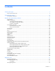
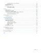
3. Connect a USB mouse to one USB connector. 4. Connect a USB keyboard to the second USB connector. Item Description 1 Monitor 2 USB mouse 3 USB keyboard 4 HP c-Class Blade SUV Cable Accessing local media devices Use the following configuration when configuring a server blade or loading software updates and patches from a USB CD/DVD-ROM. Use a USB hub when connecting a USB CD-ROM drive to the server blade. The USB hub provides additional connections. 1.
o USB mouse Item Description 1 Monitor 2 USB CD/DVD-ROM drive 3 USB keyboard 4 USB hub 5 USB mouse 6 HP c-Class Blade SUV Cable Cabling 68
Troubleshooting Troubleshooting resources The HP ProLiant Gen8 Troubleshooting Guide, Volume I: Troubleshooting provides procedures for resolving common problems and comprehensive courses of action for fault isolation and identification, issue resolution, and software maintenance on ProLiant servers and server blades. To view the guide, select a language: • English (http://www.hp.com/support/ProLiant_TSG_v1_en) • French (http://www.hp.com/support/ProLiant_TSG_v1_fr) • Spanish (http://www.hp.
Component identification Front panel components Item Description 1 Hard drive bay 1 2 Hard drive bay 2 3 Serial label pull tab 4 HP c-Class Blade SUV connector* (behind the serial label pull tab) 5 Server blade release lever 6 Server blade release button *The SUV connector and the HP c-Class Blade SUV Cable are used for some server blade configuration and diagnostic procedures.
Front panel LEDs and buttons Item Description Status 1 Health status LED bar Solid Green = Normal (System is powered on.) Flashing Green = Power On/Standby Button service is being initialized. Flashing Amber = Degraded condition Flashing Red = Critical condition Off = Normal (System is in standby.) 2 Power On/Standby Solid Green = System is powered on. button and system Flashing Green = System is waiting to power on; Power On/Standby button is power LED pressed.
Item LED Status 1 Locate Solid blue The drive is being identified by a host application. Flashing blue The drive carrier firmware is being updated or requires an update. Rotating green Drive activity Off No drive activity Solid white Do not remove the drive. Removing the drive causes one or more of the logical drives to fail. Off Removing the drive does not cause a logical drive to fail. Solid green The drive is a member of one or more logical drives.
Item Description 10 Enclosure connector 11 MicroSD card connector 12 FlexibleLOM connectors (2) 13 Processor socket 1 (populated) 14 Processor 2 DIMM slots 15 Internal USB connector 16 TPM connector The symbols correspond to the symbols located on the interconnect bays. For more information, see the HP ProLiant BL420c Gen8 Server Blade Installation Instructions on the HP website (http://www.hp.com/support).
DIMM slot locations DIMM slots are numbered sequentially (1 through 6) for each processor. The supported AMP modes use the alpha assignments for population order and the slot numbers designate the DIMM slot ID for spare replacement. DIMM identification To determine DIMM characteristics, use the label attached to the DIMM and the following illustration and table.
Item Description Definition 4 Voltage rating L = Low voltage (1.35V) U = Ultra low voltage (1.25V) Blank or omitted = Standard 5 Memory speed 12800 = 1600-MT/s 10600 = 1333-MT/s 8500 = 1066-MT/s 6 DIMM type R = RDIMM (registered) E = UDIMM (unbuffered with ECC) L = LRDIMM (load reduced) For the latest supported memory information, see the QuickSpecs on the HP website (http://h18000.www1.hp.com/products/quickspecs/ProductBulletin.html).
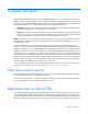
HP c-Class Blade SUV Cable Item Connector Description 1 Server blade For connecting to the SUV connector on the server blade front panel 2 Video For connecting a video monitor 3 USB For connecting up to two USB devices 4 Serial For trained personnel to connect a null modem serial cable and perform advanced diagnostic procedures Component identification 76
Specifications Environmental specifications Specification Value — Temperature range* Operating 10°C to 35°C (50°F to 95°F) Non-operating -30°C to 60°C (-22°F to 140°F) Relative humidity (noncondensing)** — Operating 10% to 90% @ 28°C (82.4°F) Non-operating 5% to 95% @ 38.7°C (101.7°F) Altitude† — Operating 3050 m (10,000 ft) Non-operating 9144 m (30,000 ft) * The following temperature conditions and limitations apply: - All temperature ratings shown are for sea level.
Acronyms and abbreviations DDR3 double data rate-3 FBWC flash-backed write cache FC Fibre Channel iLO Integrated Lights-Out IML Integrated Management Log LRDIMM load reduced dual in-line memory module POST Power-On Self Test RBSU ROM-Based Setup Utility RDIMM registered dual in-line memory module SAS serial attached SCSI SATA serial ATA SFF small form factor Acronyms and abbreviations 78
SIM Systems Insight Manager TPM Trusted Platform Module UDIMM unregistered dual in-line memory module UID unit identification USB universal serial bus Acronyms and abbreviations 79
Documentation feedback HP is committed to providing documentation that meets your needs. To help us improve the documentation, send any errors, suggestions, or comments to Documentation Feedback (mailto:docsfeedback@hp.com). Include the document title and part number, version number, or the URL when submitting your feedback.
Index A E access panel 15, 24 Active Health System 62 electrostatic discharge 21 enclosure connector 72 enclosure connector cover 15, 26, 72 environmental specifications 77 error messages 69 external cables 66 external USB functionality 64 B backplane, drive 37 backplane, hard drive 37 battery 15, 72 buttons 21, 70 C cables 65, 66 cabling 65, 66 cabling resources 65 capacitor pack 39, 40, 41 cautions 21 components 15, 21, 34, 70 components, identification 15, 70 components, mechanical 15 connectors 70
HP HP HP HP Dynamic Smart Array B320i Controller 15, 27 Insight Diagnostics 21, 62 Insight Diagnostics survey functionality 62 technical support 5 I illustrated parts catalog 15 iLO (Integrated Lights-Out) 62, 63 IML (Integrated Management Log) 63 InfiniBand mezzanine 15 Insight Diagnostics 21, 62 Integrated Lights-Out (iLO) 63 Integrated Management Log (IML) 63 internal USB functionality 64 L LED, health 71 LED, power button 71 LED, system power 71 LEDs 71 LEDs, hard drive 71 LEDs, NIC 71 LEDs, SAS hard
T T-10 Torx screwdriver 21 T-15 Torx screwdriver 21, 75 technical support 5 tool locations 75 tools 21, 75 Torx screwdriver 21, 75 TPM (Trusted Platform Module) 15, 60 troubleshooting 69 troubleshooting resources 69 troubleshooting, firmware upgrade utility 69 Trusted Platform Module (TPM) 15, 60 U USB connector 76 USB devices 66 USB support 63 utilities 61 V video connector 76 video connector cabling 76 video devices 66 W warnings 21 Index 83