HP ProLiant BL420c Gen8 Server Blade User Guide Abstract This document is for the person who installs, administers, and troubleshoots servers and storage systems. HP assumes you are qualified in the servicing of computer equipment and trained in recognizing hazards in products with hazardous energy levels.
© Copyright 2012 Hewlett-Packard Development Company, L.P. The information contained herein is subject to change without notice. The only warranties for HP products and services are set forth in the express warranty statements accompanying such products and services. Nothing herein should be construed as constituting an additional warranty. HP shall not be liable for technical or editorial errors or omissions contained herein. Microsoft® and Windows® are U.S. registered trademarks of Microsoft Corporation.
Contents Component identification ............................................................................................................... 6 Front panel components ............................................................................................................................. 6 Front panel LEDs and buttons ...................................................................................................................... 7 Drive LED definitions .........................................
HP Trusted Platform Module option ............................................................................................................ 42 Installing the Trusted Platform Module board ..................................................................................... 43 Retaining the recovery key/password .............................................................................................. 44 Enabling the Trusted Platform Module..............................................................
Modifications .......................................................................................................................................... 66 Cables ................................................................................................................................................... 66 Canadian notice (Avis Canadien) .............................................................................................................. 66 European Union regulatory notice ...................
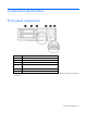
Component identification Front panel components Item Description 1 Hard drive bay 1 2 Hard drive bay 2 3 Serial label pull tab 4 HP c-Class Blade SUV connector* (behind the serial label pull tab) 5 Server blade release lever 6 Server blade release button *The SUV connector and the HP c-Class Blade SUV Cable are used for some server blade configuration and diagnostic procedures.
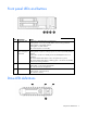
Front panel LEDs and buttons Item Description Status 1 Health status LED bar Solid Green = Normal (System is powered on.) Flashing Green = Power On/Standby Button service is being initialized. Flashing Amber = Degraded condition Flashing Red = Critical condition Off = Normal (System is in standby.) 2 Power On/Standby Solid Green = System is powered on. button and system Flashing Green = System is waiting to power on; Power On/Standby button is power LED pressed.
Item LED Status 1 Locate Solid blue The drive is being identified by a host application. Flashing blue The drive carrier firmware is being updated or requires an update. Rotating green Drive activity Off No drive activity Solid white Do not remove the drive. Removing the drive causes one or more of the logical drives to fail. Off Removing the drive does not cause a logical drive to fail. Solid green The drive is a member of one or more logical drives.
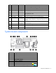
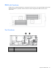
Item Description 10 Enclosure connector 11 MicroSD card connector 12 FlexibleLOM connectors (2) 13 Processor socket 1 (populated) 14 Processor 2 DIMM slots 15 Internal USB connector 16 TPM connector The symbols correspond to the symbols located on the interconnect bays. For more information, see the HP ProLiant BL420c Gen8 Server Blade Installation Instructions on the HP website (http://www.hp.com/support).
DIMM slot locations DIMM slots are numbered sequentially (1 through 6) for each processor. The supported AMP modes use the alpha assignments for population order and the slot numbers designate the DIMM slot ID for spare replacement.
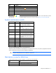
HP c-Class Blade SUV Cable Item Connector Description 1 Server blade For connecting to the SUV connector on the server blade front panel 2 Video For connecting a video monitor 3 USB For connecting up to two USB devices 4 Serial For trained personnel to connect a null modem serial cable and perform advanced diagnostic procedures Component identification 11
Operations Power up the server blade The Onboard Administrator initiates an automatic power-up sequence when the server blade is installed. If the default setting is changed, use one of the following methods to power up the server blade: • Use a virtual power button selection through iLO. • Press and release the Power On/Standby button. When the server blade goes from the standby mode to the full power mode, the system power LED changes from amber to solid green.
o poweroff server [bay number] force This form of the command forces the server blade to enter standby mode without properly exiting applications and the OS. If an application stops responding, this method forces a shutdown. • Use the Onboard Administrator GUI to initiate a shutdown: a. Select the Enclosure Information tab. b. In the Device Bays item, select the Overall checkbox. c.
Remove the access panel To remove the component: 1. Power down the server blade (on page 12). 2. Remove the server blade (on page 13). 3. Press the access panel release button. 4. Slide the access panel towards the rear of the server blade, and then lift to remove the panel. Install the access panel 1. Place the access panel on top of the server blade. 2. Slide the access panel forward until it clicks into place. Remove the SAS controller 1. Power down the server blade (on page 12). 2.
Install the SAS controller 1. Power down the server blade (on page 12). 2. Remove the server blade (on page 13). 3. Remove the access panel (on page 14). 4. Disconnect the FBWC battery pack cabling, if connected ("FBWC capacitor pack cabling" on page 46). IMPORTANT: Always close the SAS controller handle before installing the SAS controller. 5. Close the SAS controller handle and then install the SAS controller.
8. Remove the front panel/drive cage assembly. Remove the DIMM baffle 1. Power down the server blade (on page 12). 2. Remove the server blade (on page 13). 3. Remove the access panel (on page 14). 4. Disconnect the capacitor pack cabling, if connected ("FBWC capacitor pack cabling" on page 46). 5. Remove the SAS controller (on page 14). 6.
o Processor 1 DIMM baffle (left side) o Processor 2 DIMM baffle (right side) Operations 17
Setup Overview Installation of a server blade requires the following steps: 1. Install and configure an HP BladeSystem c-Class enclosure. 2. Install any server blade options. 3. Install interconnect modules in the enclosure. 4. Connect the interconnect modules to the network. 5. Install a server blade. 6. Complete the server blade configuration. Installing an HP BladeSystem c-Class enclosure Before performing any server blade-specific procedures, install an HP BladeSystem c-Class enclosure.
Interconnect bay numbering and device mapping • HP BladeSystem c7000 Enclosure To support network connections for specific signals, install an interconnect module in the bay corresponding to the FlexibleLOM or mezzanine signals.
• HP BladeSystem c3000 Enclosure and Tower Enclosure Server blade signal Interconnect bay number Interconnect bay label Notes FlexibleLOM 1 — Mezzanine 1 2 Four port cards connect to bay 2. Mezzanine 2 3 and 4 • • • Four port cards Ports 1 and 3 connect to bay 3. Ports 2 and 4 connect to bay 4.
Two types of interconnect modules are available for HP BladeSystem c-Class enclosures: Pass-Thru modules and switch modules. For more information about interconnect module options, see the HP website (http://www.hp.com/go/bladesystem/interconnects). IMPORTANT: To connect to a network with a Pass-Thru module, always connect the Pass-Thru module to a network device that supports Gigabit or 10 Gb speed, depending on the corresponding Pass-Thru model.
2. Remove the enclosure connector cover. 3. Install the server blade. Completing the configuration To complete the server blade and HP BladeSystem configuration, see the overview card that ships with the enclosure.
Hardware options installation Introduction If more than one option is being installed, read the installation instructions for all the hardware options and identify similar steps to streamline the installation process. WARNING: To reduce the risk of personal injury from hot surfaces, allow the drives and the internal system components to cool before touching them. CAUTION: To prevent damage to electrical components, properly ground the server before beginning any installation procedure.
2. Prepare the drive. 3. Install the drive. 4. Determine the status of the drive from the drive LED definitions (on page 7). Processor option WARNING: To reduce the risk of personal injury from hot surfaces, allow the drives and the internal system components to cool before touching them. CAUTION: To prevent possible server blade malfunction and damage to the equipment, multiprocessor configurations must contain processors with the same part number.
3. Remove the server blade (on page 13). 4. Remove the access panel (on page 14). 5. Disconnect the capacitor pack cabling, if connected ("FBWC capacitor pack cabling" on page 46). 6. Remove the SAS controller (on page 14). 7. Remove the heatsink blank. Retain the heatsink blank for future use. 8. Open each of the processor locking levers in the order indicated, and then open the processor retaining bracket.
9. Remove the clear processor socket cover. Retain the processor socket cover for future use. 10. Install the processor. Verify that the processor is fully seated in the processor retaining bracket by visually inspecting the processor installation guides on either side of the processor. THE PINS ON THE SYSTEM BOARD ARE VERY FRAGILE AND EASILY DAMAGED. CAUTION: THE PINS ON THE SYSTEM BOARD ARE VERY FRAGILE AND EASILY DAMAGED.
CAUTION: Do not press down on the processor. Pressing down on the processor may cause damage to the processor socket and the system board. Press only in the area indicated on the processor retaining bracket. 12. Press and hold the processor retaining bracket in place, and then close each processor locking lever. Press only in the area indicated on the processor retaining bracket. 13. Remove the thermal interface protective cover from the heatsink.
CAUTION: Heatsink retaining screws should be tightened in diagonally opposite pairs (in an "X" pattern). 14. Install the heatsink. 15. Install the SAS controller (on page 15). 16. Install the access panel (on page 14). 17. Install the server blade ("Installing a server blade" on page 21). Memory options IMPORTANT: This server blade does not support mixing LRDIMMs, RDIMMs, or UDIMMs. Attempting to mix any combination of these DIMMs can cause the server to halt during BIOS initialization.
• Quad-rank PC3L-10600 (DDR3-1333) LRDIMMs, operating as dual-rank DIMMs, at up to 1333 MT/s Speed, voltage, and capacity DIMM type DIMM rank DIMM capacity Native speed (MT/s) Voltage RDIMM Single-rank 4 GB 1600 STD RDIMM Dual-rank 8 GB 1333 LV RDIMM Single-rank 8 GB 1600 STD RDIMM Dual-rank 16 GB 1333 LV RDIMM Dual-rank 16 GB 1600 STD LRDIMM Quad-rank 32 GB 1333 LV UDIMM Single-rank 2 GB 1333 LV UDIMM Dual-rank 4 GB 1333 LV UDIMM Dual-rank 8 GB 1333 LV De
DIMM slots in this server are identified by number and by letter. Letters identify the population order. Slot numbers indicate the DIMM slot ID for spare replacement. Channel Slot designation Slot number 1 A D 1 2 2 B E 3 4 3 C F 5 6 This multichannel architecture provides enhanced performance in advanced ECC mode. For the location of the slot numbers, see "DIMM Slots ("DIMM slot locations" on page 10)".
DIMM identification To determine DIMM characteristics, use the label attached to the DIMM and the following illustration and table. Item Description Definition 1 Size — 2 Rank 1R = Single-rank 2R = Dual-rank 4R = Quad-rank 3 Data width x4 = 4-bit x8 = 8-bit 4 Voltage rating L = Low voltage (1.35v) U = Ultra low voltage (1.
is degrading. This allows DIMMs that have a higher probability of receiving an uncorrectable memory error (which would result in system downtime) to be removed from operation. Advanced Memory Protection options are configured in RBSU. If the requested AMP mode is not supported by the installed DIMM configuration, the server blade boots in Advanced ECC mode. For more information, see "HP ROM-Based Setup Utility (on page 56).
Lockstep memory configuration Lockstep mode provides protection against multi-bit memory errors that occur on the same DRAM device. Lockstep mode can correct any single DRAM device failure on x4 and x8 DIMM types. The DIMMs in each channel must have identical HP part numbers. General DIMM slot population guidelines Observe the following guidelines for all AMP modes: • Install DIMMs only if the corresponding processor is installed.
Lockstep Memory population guidelines For Lockstep memory mode configurations, observe the following guidelines: • Observe the general DIMM slot population guidelines (on page 33). • Always install DIMMs in channel 2 and 3 for each installed processor. • Do not install DIMMs in channel 1 for any processor. • DIMM configuration on channel 2 and channel 3 of a processor must be identical. • In multi-processor configurations, each processor must have a valid Lockstep Memory mode configuration.
9. Install the DIMM. 10. Install all DIMM baffles. 11. Install the SAS controller (on page 15). 12. Install the access panel (on page 14). To configure the memory mode, use RBSU ("HP ROM-Based Setup Utility" on page 56). Mezzanine card option Optional mezzanine cards are classified as Type A mezzanine cards and Type B mezzanine cards. The type of the mezzanine card determines where it can be installed in the server blade.
4. Remove the mezzanine assembly from the server blade. 5. Align the mezzanine card with the guide pins on the mezzanine assembly.
6. Install the mezzanine card in the mezzanine assembly, and then tighten the mezzanine card screws to secure the card to the mezzanine assembly. 7. Align the mezzanine assembly with the guide pins on the system board, and then install the mezzanine assembly on the system board. 8. Press down firmly on the mezzanine assembly handles, and then close the mezzanine assembly latch. 9. Install the access panel (on page 14). 10. Install the server blade ("Installing a server blade" on page 21).
5. If another SAS controller is installed, do the following: a. Flush the original cache to remove all data. For more information, see the Configuring Arrays on HP Smart Array Controllers Reference Guide on the HP website (http://www.hp.com/support/SAC_UG_ProLiantServers_en). CAUTION: Always be sure that both captive screws are disengaged before removing the SAS controller. Failure to disengage the screws may result in damage to the SAS controller. b.
6. Close the SAS controller handle and then install the SAS controller. To properly seat the SAS controller, press firmly in the areas indicated on the SAS controller. 7. Install the capacitor pack.
8. Route the capacitor pack cable and connect the cable to the SAS controller. 9. Install the access panel (on page 14). 10. Install the server blade ("Installing a server blade" on page 21). FBWC capacitor pack option To install the component: 1. Power down the server blade (on page 12). 2. Remove the server blade (on page 13). 3. Remove the access panel (on page 14). 4.
o 5. FBWC capacitor pack for the cache module or the SAS controller option Route the FBWC capacitor pack cable. The DIMM baffles may be removed to route the cables, if necessary. o Route the cable along the Processor 2 DIMM baffle and connect the cable to the mezzanine option.
o Route the cable along the Processor 1 DIMM baffle and connect the cable to the cache module. o Route the cable along the Processor 2 DIMM baffle and connect the cable to the SAS controller option. 6. Install the access panel (on page 14). 7. Install the server blade ("Installing a server blade" on page 21). HP Trusted Platform Module option Use these instructions to install and enable a TPM on a supported server blade. This procedure includes three sections: 1.
TPM installation requires the use of drive encryption technology, such as the Microsoft Windows BitLocker Drive Encryption feature. For more information on BitLocker, see the Microsoft website (http://www.microsoft.com). CAUTION: Always observe the guidelines in this document. Failure to follow these guidelines can cause hardware damage or halt data access. When installing or replacing a TPM, observe the following guidelines: • Do not remove an installed TPM.
10. Install the TPM board. Press down on the connector to seat the board ("System board components" on page 8). 11. Install the TPM security rivet by pressing the rivet firmly into the system board. 12. Install the front panel/drive cage assembly. 13. Install the DIMM baffle. 14. Install the SAS controller (on page 15). 15. Install the access panel (on page 14). 16. Install the server blade ("Installing a server blade" on page 21). 17. Power up the server blade (on page 12).
To help ensure maximum security, observe the following guidelines when retaining the recovery key/password: • Always store the recovery key/password in multiple locations. • Always store copies of the recovery key/password away from the server blade. • Do not save the recovery key/password on the encrypted hard drive. Enabling the Trusted Platform Module 1. When prompted during the start-up sequence, access RBSU by pressing the F9 key. 2. From the Main Menu, select Server Security. 3.
Cabling Cabling resources Cabling configurations and requirements vary depending on the product and installed options. For more information about product features, specifications, options, configurations, and compatibility, see the QuickSpecs on the HP website (http://h18000.www1.hp.com/products/quickspecs/ProductBulletin.html). At the website, choose the geographic region, and then locate the product by name or product category.
• SAS controller option For capacitor pack and cabling instructions, see "FBWC capacitor pack ("FBWC capacitor pack option" on page 40)." Using the HP c-Class Blade SUV Cable The HP c-Class Blade SUV Cable enables the user to perform server blade administration, configuration, and diagnostic procedures by connecting video and USB devices directly to the server blade. For SUV cable connectors, see "HP c-Class Blade SUV Cable (on page 11).
3. Connect a USB mouse to one USB connector. 4. Connect a USB keyboard to the second USB connector. Item Description 1 Monitor 2 USB mouse 3 USB keyboard 4 HP c-Class Blade SUV Cable Accessing local media devices Use the following configuration when configuring a server blade or loading software updates and patches from a USB CD/DVD-ROM. Use a USB hub when connecting a USB CD-ROM drive to the server blade. The USB hub provides additional connections. 1.
o USB mouse Item Description 1 Monitor 2 USB CD/DVD-ROM drive 3 USB keyboard 4 USB hub 5 USB mouse 6 HP c-Class Blade SUV Cable Cabling 49
Troubleshooting Troubleshooting resources The HP ProLiant Gen8 Troubleshooting Guide, Volume I: Troubleshooting provides procedures for resolving common problems and comprehensive courses of action for fault isolation and identification, issue resolution, and software maintenance on ProLiant servers and server blades. To view the guide, select a language: • English (http://www.hp.com/support/ProLiant_TSG_v1_en) • French (http://www.hp.com/support/ProLiant_TSG_v1_fr) • Spanish (http://www.hp.
Software and configuration utilities Server mode The software and configuration utilities presented in this section operate in online mode, offline mode, or in both modes.
iLO enables and manages the Active Health System (on page 52) and also features Agentless Management. All key internal subsystems are monitored by iLO. SNMP alerts are sent directly by iLO regardless of the host operating system or even if no host operating system is installed. HP Insight Remote Support software (on page 55) is also available in HP iLO with no operating system software, drivers, or agents.
The data that is collected is managed according to the HP Data Privacy policy. For more information see the HP website (http://www.hp.com/go/privacy). The Active Health System log, in conjunction with the system monitoring provided by Agentless Management or SNMP Pass-thru, provides continuous monitoring of hardware and configuration changes, system status, and service alerts for various server components. The Agentless Management Service is available in the SPP, which is a disk image (.
HP Insight Diagnostics HP Insight Diagnostics is a proactive server blade management tool, available in both offline and online versions, that provides diagnostics and troubleshooting capabilities to assist IT administrators who verify server blade installations, troubleshoot problems, and perform repair validation. HP Insight Diagnostics Offline Edition performs various in-depth system and component testing while the OS is not running.
HP Insight Remote Support software HP strongly recommends that you install HP Insight Remote Support software to complete the installation or upgrade of your product and to enable enhanced delivery of your HP Warranty, HP Care Pack Service, or HP contractual support agreement.
For more information or to download SPP, see the HP website (http://www.hp.com/go/spp). HP Smart Update Manager The HP SUM provides intelligent and flexible firmware and software deployment. This technology assists in reducing the complexity of provisioning and updating HP ProLiant Servers, options, and Blades within the data center. HP SUM is used to deploy firmware and software in SPP. HP SUM enables system administrators to upgrade ROM images efficiently across a wide range of server blades and options.
• To access RBSU, press the F9 key during power-up when prompted. • To navigate the menu system, use the arrow keys. • To make selections, press the Enter key. • To access Help for a highlighted configuration option, press the F1 key. IMPORTANT: RBSU automatically saves settings when you press the Enter key. The utility does not prompt you for confirmation of settings before you exit the utility. To change a selected setting, you must select a different setting and press the Enter key.
• Access the boot menu by pressing the F11 key. • Force a PXE Network boot by pressing the F12 key. Configuring AMP modes Not all ProLiant servers support all AMP modes. RBSU provides menu options only for the modes supported by the server. Advanced memory protection within RBSU enables the following advanced memory modes: • Advanced ECC Mode—Provides memory protection beyond Standard ECC. All single-bit failures and some multi-bit failures can be corrected without resulting in system downtime.
• Supports online array capacity expansion, logical drive extension, assignment of online spares, and RAID or stripe size migration • Suggests the optimum configuration for an unconfigured system • For supported controllers, provides access to licensed features, including: o Moving and deleting individual logical volumes o Advanced Capacity Expansion (SATA to SAS and SAS to SATA) o Offline Split Mirror o RAID 6 and RAID 60 o RAID 1 (ADM) and RAID 10 (ADM) o HP Drive Erase o Video-On-Demand
• Setting the controller to be the boot controller • Selecting the boot volume If you do not use the utility, ORCA will default to the standard configuration. For more information regarding the default configurations that ORCA uses, see the HP ROM-Based Setup Utility User Guide on the Documentation CD or the HP website (http://www.hp.com/support/rbsu).
• Diagnostics • DOS • Operating environments which do not provide native USB support Redundant ROM support The server blade enables you to upgrade or configure the ROM safely with redundant ROM support. The server blade has a single ROM that acts as two separate ROM images. In the standard implementation, one side of the ROM contains the current ROM program version, while the other side of the ROM contains a backup version.
Software and firmware Software and firmware should be updated before using the server for the first time, unless any installed software or components require an older version. For system software and firmware updates, download the SPP ("HP Service Pack for ProLiant" on page 55) from the HP website (http://www.hp.com/go/spp). Version control The VCRM and VCA are web-enabled Insight Management Agents tools that HP SIM uses to schedule software update tasks to the entire enterprise.
Battery replacement If the server blade no longer automatically displays the correct date and time, you may need to replace the battery that provides power to the real-time clock. Under normal use, battery life is 5 to 10 years. WARNING: The computer contains an internal lithium manganese dioxide, a vanadium pentoxide, or an alkaline battery pack. A risk of fire and burns exists if the battery pack is not properly handled.
For more information about battery replacement or proper disposal, contact an authorized reseller or an authorized service provider.
Regulatory compliance notices Regulatory compliance identification numbers For the purpose of regulatory compliance certifications and identification, this product has been assigned a unique regulatory model number. The regulatory model number can be found on the product nameplate label, along with all required approval markings and information. When requesting compliance information for this product, always refer to this regulatory model number.
radio communications. However, there is no guarantee that interference will not occur in a particular installation. If this equipment does cause harmful interference to radio or television reception, which can be determined by turning the equipment off and on, the user is encouraged to try to correct the interference by one or more of the following measures: • Reorient or relocate the receiving antenna. • Increase the separation between the equipment and receiver.
This Class A digital apparatus meets all requirements of the Canadian Interference-Causing Equipment Regulations. Cet appareil numérique de la classe A respecte toutes les exigences du Règlement sur le matériel brouilleur du Canada. Class B equipment This Class B digital apparatus meets all requirements of the Canadian Interference-Causing Equipment Regulations. Cet appareil numérique de la classe B respecte toutes les exigences du Règlement sur le matériel brouilleur du Canada.
This symbol on the product or on its packaging indicates that this product must not be disposed of with your other household waste. Instead, it is your responsibility to dispose of your waste equipment by handing it over to a designated collection point for the recycling of waste electrical and electronic equipment.
Class B equipment Chinese notice Class A equipment Vietnam compliance marking notice This marking is for applicable products only. Ukraine notice Laser compliance This product may be provided with an optical storage device (that is, CD or DVD drive) and/or fiber optic transceiver. Each of these devices contains a laser that is classified as a Class 1 Laser Product in accordance with US FDA regulations and the IEC 60825-1. The product does not emit hazardous laser radiation.
WARNING: Use of controls or adjustments or performance of procedures other than those specified herein or in the laser product's installation guide may result in hazardous radiation exposure. To reduce the risk of exposure to hazardous radiation: • Do not try to open the module enclosure. There are no user-serviceable components inside. • Do not operate controls, make adjustments, or perform procedures to the laser device other than those specified herein.
Nach ISO 7779:1999 (Typprüfung) Regulatory compliance notices 71
Electrostatic discharge Preventing electrostatic discharge To prevent damaging the system, be aware of the precautions you need to follow when setting up the system or handling parts. A discharge of static electricity from a finger or other conductor may damage system boards or other static-sensitive devices. This type of damage may reduce the life expectancy of the device. To prevent electrostatic damage: • Avoid hand contact by transporting and storing products in static-safe containers.
Specifications Environmental specifications Specification Value — Temperature range* Operating 10°C to 35°C (50°F to 95°F) Non-operating -30°C to 60°C (-22°F to 140°F) Relative humidity (noncondensing)** — Operating 10% to 90% @ 28°C (82.4°F) Non-operating 5% to 95% @ 38.7°C (101.7°F) Altitude† — Operating 3050 m (10,000 ft) Non-operating 9144 m (30,000 ft) * The following temperature conditions and limitations apply: - All temperature ratings shown are for sea level.
Support and other resources Before you contact HP Be sure to have the following information available before you call HP: • Active Health System log Download and have available an Active Health System log for 3 days before the failure was detected. For more information, see the HP iLO 4 User Guide or HP Intelligent Provisioning User Guide on the HP website (http://www.hp.com/go/ilo/docs).
providers or service partners) identifies that the repair can be accomplished by the use of a CSR part, HP will ship that part directly to you for replacement. There are two categories of CSR parts: • Mandatory—Parts for which customer self repair is mandatory. If you request HP to replace these parts, you will be charged for the travel and labor costs of this service. • Optional—Parts for which customer self repair is optional. These parts are also designed for customer self repair.
Pour plus d'informations sur le programme CSR de HP, contactez votre Mainteneur Agrée local. Pour plus d'informations sur ce programme en Amérique du Nord, consultez le site Web HP (http://www.hp.com/go/selfrepair). Riparazione da parte del cliente Per abbreviare i tempi di riparazione e garantire una maggiore flessibilità nella sostituzione di parti difettose, i prodotti HP sono realizzati con numerosi componenti che possono essere riparati direttamente dal cliente (CSR, Customer Self Repair).
HINWEIS: Einige Teile sind nicht für Customer Self Repair ausgelegt. Um den Garantieanspruch des Kunden zu erfüllen, muss das Teil von einem HP Servicepartner ersetzt werden. Im illustrierten Teilekatalog sind diese Teile mit „No“ bzw. „Nein“ gekennzeichnet. CSR-Teile werden abhängig von der Verfügbarkeit und vom Lieferziel am folgenden Geschäftstag geliefert. Für bestimmte Standorte ist eine Lieferung am selben Tag oder innerhalb von vier Stunden gegen einen Aufpreis verfügbar.
sustituciones que lleve a cabo el cliente, HP se hará cargo de todos los gastos de envío y devolución de componentes y escogerá la empresa de transporte que se utilice para dicho servicio. Para obtener más información acerca del programa de Reparaciones del propio cliente de HP, póngase en contacto con su proveedor de servicios local. Si está interesado en el programa para Norteamérica, visite la página web de HP siguiente (http://www.hp.com/go/selfrepair).
Opcional – Peças cujo reparo feito pelo cliente é opcional. Essas peças também são projetadas para o reparo feito pelo cliente. No entanto, se desejar que a HP as substitua, pode haver ou não a cobrança de taxa adicional, dependendo do tipo de serviço de garantia destinado ao produto. OBSERVAÇÃO: Algumas peças da HP não são projetadas para o reparo feito pelo cliente. A fim de cumprir a garantia do cliente, a HP exige que um técnico autorizado substitua a peça.
Support and other resources 80
Support and other resources 81
Acronyms and abbreviations ABEND abnormal end ACU Array Configuration Utility ADM Advanced Data Mirroring AMP Advanced Memory Protection ASR Automatic Server Recovery FBWC flash-backed write cache iLO Integrated Lights-Out IML Integrated Management Log LRDIMM Load Reduced dual in-line memory module LV DIMM Low voltage DIMM ORCA Option ROM Configuration for Arrays POST Power-On Self Test Acronyms and abbreviations 82
PXE Preboot Execution Environment RBSU ROM-Based Setup Utility RDIMM registered dual in-line memory module SAS serial attached SCSI SATA serial ATA SIM Systems Insight Manager UDIMM unregistered dual in-line memory module UID unit identification USB universal serial bus VCA Version Control Agent Acronyms and abbreviations 83
Documentation feedback HP is committed to providing documentation that meets your needs. To help us improve the documentation, send any errors, suggestions, or comments to Documentation Feedback (mailto:docsfeedback@hp.com). Include the document title and part number, version number, or the URL when submitting your feedback.
Index A access panel 14 acoustics statement for Germany 70 ACU (Array Configuration Utility) 51, 58 Advanced ECC memory 32, 33, 58 Array Configuration Utility (ACU) 58 ASR (Automatic Server Recovery) 60 authorized reseller 74 auto-configuration process 57 Automatic Server Recovery (ASR) 60 B Basic Input/Output System (BIOS) 51, 60 batteries, replacing 63, 70 battery 8, 63, 70 battery replacement notice 70 before you contact HP 74 BIOS (Basic Input/Output System) 51, 60 BIOS upgrade 51, 60 blade blank 21 bo
FCC (Federal Communications Commission) notice 65, 66 FCC rating label 65 features 6, 58 Federal Communications Commission (FCC) notice 65, 66 firmware 62 firmware update 55, 62 firmware upgrade utility, troubleshooting 50 firmware, updating 55, 62 firmware, upgrading 62 FlexibleLOM connectors 8 FlexibleLOM LED 7 front panel buttons 7 front panel components 6 front panel LEDs 7 front panel/drive cage assembly 15 G grounding methods 72 H hard drive backplane connector 8 hard drive bays 6 hard drive LEDs 7
memory, configuration requirements 31, 34 memory, configuring 31, 32, 33 memory, lockstep 33, 34 memory, online spare 32, 58 mezzanine board connectors 8 mezzanine boards 35 mezzanine card 35 mezzanine connector covers 35 mezzanine connectors 8, 9 modifications, FCC notice 66 N network connections 20 NIC (network interface card) 8 O online spare memory 32, 58 online spare population guidelines 33 operating systems 62 operations 12 Option ROM Configuration for Arrays (ORCA) 51, 59 options 18, 51 options in
System Erase Utility 54 system maintenance switch 8, 9 system, keeping current 61 T T-15 Torx screwdriver 10 Taiwan battery recycling notice 70 technical support 74 telephone numbers 74 tool locations 10 tool, DIMM 10 tools 10 Torx screwdriver 10 TPM (Trusted Platform Module) 42, 43, 44, 45 troubleshooting 50 troubleshooting resources 50 troubleshooting, firmware upgrade utility 50 Trusted Platform Module (TPM) 42, 43, 44, 45 U Ukraine notice 69 updating the system ROM 61 USB connectors 11 USB devices 47