HP ProLiant BL460c G6 Server Blade User Guide Abstract This document is for the person who installs, administers, and troubleshoots servers and storage systems. HP assumes you are qualified in the servicing of computer equipment and trained in recognizing hazards in products with hazardous energy levels.
© Copyright 2009, 2011 Hewlett-Packard Development Company, L.P. The information contained herein is subject to change without notice. The only warranties for HP products and services are set forth in the express warranty statements accompanying such products and services. Nothing herein should be construed as constituting an additional warranty. HP shall not be liable for technical or editorial errors or omissions contained herein. Microsoft, Windows, and Windows Server are U.S.
Contents Component identification ............................................................................................................... 6 Front panel components ............................................................................................................................. 6 Front panel LEDs ....................................................................................................................................... 7 SAS and SATA hard drive LEDs..............................
Using the HP c-Class Blade SUV Cable ...................................................................................................... 45 Connecting locally to a server blade with video and USB devices .................................................................. 45 Accessing a server blade with local KVM ......................................................................................... 46 Accessing local media devices ........................................................................
POST error messages and beep codes ....................................................................................................... 81 Battery replacement .................................................................................................................... 83 Regulatory compliance notices ..................................................................................................... 85 Regulatory compliance identification numbers .................................................
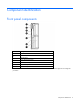
Component identification Front panel components Item Description 1 SUV connector* 2 Serial label pull tab 3 Release button 4 Server blade release lever 5 Power On/Standby button 6 Hard drive bay 1 7 Hard drive bay 2 *The SUV connector and the HP c-Class Blade SUV Cable are for some server blade configuration and diagnostic procedures.
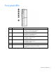
Front panel LEDs Item Description Status 1 UID LED Blue = Identified Blue flashing = Active remote management Off = No active remote management 2 Health LED Green = Normal Amber flashing = Degraded condition Red flashing = Critical condition 3 Flex-10 NIC 1 LED* Green = Network linked Green flashing = Network activity Off = No link or activity 4 Flex-10 NIC 2 LED* Green = Network linked Green flashing = Network activity Off = No link or activity 5 Reserved — 6 System power LED Green = O
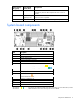
SAS and SATA hard drive LEDs Item Description 1 Fault/UID LED (amber/blue) 2 Online LED (green) SAS and SATA hard drive LED combinations Online/activity LED (green) Fault/UID LED (amber/blue) Interpretation On, off, or flashing Alternating amber and blue The drive has failed, or a predictive failure alert has been received for this drive; it also has been selected by a management application.
Online/activity LED (green) Fault/UID LED (amber/blue) Interpretation Off Steadily amber A critical fault condition has been identified for this drive, and the controller has placed it offline. Replace the drive as soon as possible. Off Amber, flashing regularly (1 Hz) A predictive failure alert has been received for this drive. Replace the drive as soon as possible. Off Off The drive is offline, a spare, or not configured as part of an array.
Mezzanine connector definitions A PCIe x8 mezzanine connector supports x16 cards at up to x8 speeds. Item PCIe Mezzanine connector 1 x8, Type I mezzanine card only Mezzanine connector 2 x8, Type 1 or II mezzanine card DIMM slot locations DIMM slots are numbered sequentially (1 through 6) for each processor. The supported AMP modes use the letter assignments for population guidelines.
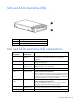
HP c-Class Blade SUV Cable Item Connector Description 1 Server blade For connecting to the SUV connector on the server blade front panel 2 Video For connecting a video monitor 3 USB For connecting up to two USB devices 4 Serial For trained personnel to connect a null modem serial cable and perform advanced diagnostic procedures Component identification 11
Operations Power up the server blade The Onboard Administrator initiates an automatic power-up sequence when the server blade is installed. If the default setting is changed, use one of the following methods to power up the server blade: • Use a virtual power button selection through iLO 2. • Press and release the Power On/Standby button. When the server blade goes from the standby mode to the full power mode, the system power LED changes from amber to green.
a. Select the Enclosure Information tab, and then select the Overall checkbox in the Device Bays item. b. Initiate a shutdown from the Virtual Power menu: — Select Momentary Press to initiate a controlled shutdown of applications and the OS. — Select Press and Hold to initiate an emergency shutdown of applications and the OS. IMPORTANT: When the server blade is in standby mode, auxiliary power is still being provided. To remove all power from the server blade, remove the server blade from the enclosure.
Remove the access panel To remove the component: 1. Power down the server blade (on page 12). 2. Remove the server blade (on page 13). 3. Lift the access panel latch and slide the access panel to the rear. 4. Remove the access panel. WARNING: To reduce the risk of personal injury from hot surfaces, allow the drives and the internal system components to cool before touching them.
Setup Overview Installation of a server blade requires the following steps: 1. Install and configure an HP BladeSystem c-Class enclosure. 2. Install any server blade options. 3. Install interconnect modules in the enclosure. 4. Connect the interconnect modules to the network. 5. Install a server blade. 6. Complete the server blade configuration. For definitions of the acronyms used in this document, refer to "Acronyms and abbreviations" in the server blade user guide.
Interconnect bay numbering and device mapping • HP BladeSystem c7000 Enclosure To support network connections for specific signals, install an interconnect module in the bay corresponding to the embedded NIC or mezzanine signals.
• HP BladeSystem c3000 Enclosure and Tower Enclosure Server blade signal Interconnect bay number Interconnect bay label Notes Flex-10 NIC 1, 2 (embedded) 1 — Mezzanine 1 2 Four port cards connect to bay 2 Mezzanine 2 3,4 • • • Four port cards Ports 1 and 3 connect to bay 3 Ports 2 and 4 connect to bay 4 For detailed port mapping information, see the HP BladeSystem enclosure installation poster or the HP BladeSystem enclosure setup and installation guide on the HP website (http://www.hp.
Connecting to the network To connect the HP BladeSystem to a network, each enclosure must be configured with network interconnect devices to manage signals between the server blades and the external network. Two types of interconnect modules are available for HP BladeSystem c-Class enclosures: Pass-Thru modules and switch modules. For more information about interconnect module options, see the HP website (http://www.hp.com/go/bladesystem/interconnects).
2. Remove the enclosure connector cover. 3. Prepare the server blade for installation.
4. Install the server blade.
Hardware options installation Introduction If more than one option is being installed, read the installation instructions for all the hardware options and identify similar steps to streamline the installation process. WARNING: To reduce the risk of personal injury from hot surfaces, allow the drives and the internal system components to cool before touching them. CAUTION: To prevent damage to electrical components, properly ground the server before beginning any installation procedure.
2. Prepare the hard drive. 3. Install the hard drive. 4. Determine the status of the hard drive from the hot-plug SAS hard drive LED combinations ("SAS and SATA hard drive LED combinations" on page 8). Processor option WARNING: To reduce the risk of personal injury from hot surfaces, allow the drives and the internal system components to cool before touching them.
IMPORTANT: Processor socket 1 must always be populated. If processor socket 1 is empty, the server blade does not power up. To install the component: 1. Update the system ROM using any standard ROM flash mechanism. 2. Power down the server blade (on page 12). 3. Remove the server blade (on page 13). 4. Remove the access panel (on page 14). 5. Remove all DIMM baffles ("Remove the DIMM baffle" on page 14). 6. Remove the heatsink blank. Retain the heatsink blank for future use.
7. Open the processor locking lever and the processor socket retaining bracket. Do not remove the processor socket cover. IMPORTANT: Be sure the processor remains inside the processor installation tool. 8. If the processor has separated from the installation tool, carefully re-insert the processor in the tool. Handle the processor by the edges only, and do not touch the bottom of the processor, especially the contact area.
9. Align the processor installation tool with the socket, and then install the processor. THE PINS ON THE SYSTEM BOARD ARE VERY FRAGILE AND EASILY DAMAGED. CAUTION: THE PINS ON THE SYSTEM BOARD ARE VERY FRAGILE AND EASILY DAMAGED. To avoid damage to the system board: • Never install or remove a processor without using the processor installation tool. • Do not touch the processor socket contacts. • Do not tilt or slide the processor when lowering the processor into the socket.
10. Press the tabs on the processor installation tool to separate it from the processor, and then remove the tool. 11. Close the processor socket retaining bracket and the processor locking lever. The processor socket cover is automatically ejected. Remove the cover. CAUTION: Be sure to close the processor socket retaining bracket before closing the processor locking lever. The lever should close without resistance.
12. Remove the thermal interface protective cover from the heatsink. 13. Align and install the heatsink. Alternate tightening the screws until the heatsink is seated properly. 14. Install all DIMM baffles. 15. Install the access panel (on page 14). Memory options IMPORTANT: This server blade does not support mixing RDIMMs and UDIMMs. Attempting to mix these two types causes the server to halt during BIOS initialization. The memory subsystem in this server blade can support RDIMMs or UDIMMs.
• Single- and dual-rank PC3-10600 (DDR-1333) DIMMs operating at 1333 and 1066 MHz • Quad-rank PC3-8500 (DDR-1067) DIMMs operating at 1066 MHz Depending on the processor model, the number of DIMMs installed, and whether UDIMMs or RDIMMs are installed, the memory clock speed may be reduced to 1066 or 800 MHz. For more information on the effect of DIMM slot population, see "General DIMM slot population guidelines (on page 31).
The memory subsystem may be populated with either RDIMMs or UDIMMs, but mixing the two types is not supported. To determine DIMM characteristics, use the label attached to the DIMM and the following illustration and table.
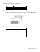
For the latest memory configuration information, see the QuickSpecs on the HP website (http://www.hp.com). RDIMM maximum memory configurations The following table lists the maximum memory configuration possible with 8-GB RDIMMs.
General DIMM slot population guidelines Observe the following guidelines for all AMP modes: • Populate DIMM slots for a processor only if the processor is installed. • To maximize performance in multi-processor configurations, distribute the total memory capacity between all processors as evenly as possible. • Do not mix Unbuffered and Registered PC3 DIMMs. • Each channel supports up to two Unbuffered DIMMs.
• Do not install DIMMs in channel 3 for any processor. • DIMMs installed on channel 1 and channel 2 of an installed processor must be identical. • In multi-processor configurations, each processor must have a valid Mirrored Memory configuration. • In multi-processor configurations, each processor may have a different valid Mirrored Memory configuration.
• DIMM configuration on channel 1 and channel 2 of a processor must be identical. • In multi-processor configurations, each processor must have a valid Lockstep Memory configuration. • In multi-processor configurations, each processor may have a different valid Lockstep Memory configuration.
4. Remove all DIMM baffles ("Remove the DIMM baffle" on page 14). 5. Open the DIMM slot latches. 6. Install the DIMM. 7. Install all DIMM baffles. 8. Install the access panel (on page 14). If you are installing DIMMs in a mirrored or lock-step configuration, configure this mode in RBSU ("HP ROM-Based Setup Utility" on page 55). Mezzanine card option Optional mezzanine cards are classified as Type I mezzanine cards and Type II mezzanine cards.
4. Remove the mezzanine connector cover. 5. Install the mezzanine card. Press down on the connector to seat the board. 6. Install the access panel (on page 14). 7. Install the server blade ("Installing a server blade" on page 18). Cache module and battery pack option The optional BBWC enabler provides the system with a means for storing and saving data in the event of an unexpected system shutdown. To install the component: 1. Back up all data on the hard drive. 2.
4. Remove the access panel (on page 14). 5. Remove all hard drives ("Hard drive option" on page 21). 6. Remove the hard drive backplane. 7. Remove the two T-15 screws from the front panel/hard drive cage assembly. 8. Remove the front panel/hard drive cage assembly.
9. Connect the BBWC battery pack cable to the cache module. 10. Install the cache module. 11. Route the BBWC battery pack cable ("BBWC battery pack cabling" on page 45).
12. Install the battery pack. 13. Install the front panel/hard drive cage assembly. 14. Install the two T-15 screws to secure the front panel/hard drive cage assembly to the chassis.
15. Install the hard drive backplane. Press down on the hard drive backplane retainer to seat the board. 16. Install the hard drives ("Hard drive option" on page 21). 17. Install the access panel (on page 14). 18. Install the server blade ("Installing a server blade" on page 18). HP Trusted Platform Module option Use these instructions to install and enable a TPM on a supported server blade. This procedure includes three sections: 1. Installing the Trusted Platform Module board (on page 40). 2.
• Any attempt to remove an installed TPM from the system board breaks or disfigures the TPM security rivet. Upon locating a broken or disfigured rivet on an installed TPM, administrators should consider the system compromised and take appropriate measures to ensure the integrity of the system data. • When using BitLocker™, always retain the recovery key/password. The recovery key/password is required to enter Recovery Mode after BitLocker™ detects a possible compromise of system integrity.
8. Remove the front panel/hard drive cage assembly. CAUTION: Any attempt to remove an installed TPM from the system board breaks or disfigures the TPM security rivet. Upon locating a broken or disfigured rivet on an installed TPM, administrators should consider the system compromised and take appropriate measures to ensure the integrity of the system data. 9. Install the TPM board. Press down on the connector to seat the board ("System board components" on page 9).
10. Install the TPM security rivet by pressing the rivet firmly into the system board. 11. Install the front panel/hard drive cage assembly. 12. Install the two T-15 screws to secure the front panel/hard drive cage assembly to the chassis.
13. Install the hard drive backplane. Press down on the hard drive backplane retainer to seat the board. 14. Install the access panel (on page 14). 15. Install the server blade ("Installing a server blade" on page 18). 16. Power up the server blade (on page 12). Retaining the recovery key/password The recovery key/password is generated during BitLocker™ setup, and can be saved and printed after BitLocker™ is enabled. When using BitLocker™, always retain the recovery key/password.
CAUTION: When a TPM is installed and enabled on the server blade, data access is locked if you fail to follow the proper procedures for updating the system or option firmware, replacing the system board, replacing a hard drive, or modifying OS application TPM settings. For more information on firmware updates and hardware procedures, see the HP Trusted Platform Module Best Practices White Paper on the HP website (http://www.hp.com/support).
Cabling BBWC battery pack cabling • Cache module cabling: Use the 24-inch BBWC battery pack cable. • Mezzanine card cabling: Use the 11.5-inch BBWC battery pack cable. Using the HP c-Class Blade SUV Cable The HP c-Class Blade SUV Cable enables the user to perform server blade administration, configuration, and diagnostic procedures by connecting video and USB devices directly to the server blade. For SUV cable connectors, see "HP c-Class Blade SUV Cable (on page 11).
• USB mouse • USB CD/DVD-ROM drive • USB diskette drive Numerous configurations are possible. This section offers two possible configurations. For more information, see "USB support and functionality (on page 60)." Accessing a server blade with local KVM For this configuration, a USB hub is not necessary. To connect additional devices, use a USB hub. CAUTION: Before disconnecting the SUV cable from the connector, always squeeze the release buttons on the sides of the connector.
1. Connect the HP c-Class Blade SUV cable to the server blade. 2. Connect the video connector to a monitor. 3. Connect a USB hub to one USB connector. 4.
Software and configuration utilities Server blade deployment tools Software drivers and additional components HP offers the following additional software components for server blades: • Health and Wellness driver and IML viewer • iLO 2 Management interface driver • Rack infrastructure interface service For Microsoft® Windows® OS users, these items are included in the HP ProLiant iLO 2 Standard Blade Edition, available from the HP website (http://www.hp.com/servers/lights-out).
The c-Class tab enables you to control specific settings for the HP BladeSystem. iLO 2 also provides web-based status for the HP BladeSystem configuration. For detailed information about iLO 2, refer to the HP Integrated Lights-Out User Guide on the HP website (http://www.hp.com/servers/lights-out). Network-based PXE deployment PXE is a component of the Intel® WfM specification. The PXE model enables server blades to load and execute an NBP from a PXE server and to execute a pre-configured image.
o Any of the following Java™ Runtime Environment versions: 1.3.1_02 1.3.1_07 1.3.1_08 1.4.1 for Windows® users only 1.4.2 for Linux users only Access the Java™ Runtime Environment versions at the HP website (http://java.sun.com/products/archive/index.html).
Deployment methods Four primary deployment methods are supported: IMPORTANT: To deploy a server blade without the HP Insight Control server deployment, create a bootable diskette or image of a bootable diskette. • PXE deployment (on page 51) • CD-ROM deployment (on page 52) • Diskette image deployment (on page 53) • SAN configuration (on page 54) PXE deployment PXE enables server blades to load an image over the network from a PXE server, and then execute it in memory.
SmartStart Scripting Toolkit The SmartStart Scripting Toolkit is a server deployment product that allows you to build an unattended automated installation for high-volume server deployments. The SmartStart Scripting Toolkit is designed to support ProLiant BL, ML, DL, and SL servers. The toolkit includes a modular set of utilities and important documentation that describes how to apply these tools to build an automated server deployment process.
To deploy with a boot CD: 1. Use the HP c-Class Blade SUV Cable to connect a USB CD-ROM drive to the server blade. Refer to "Connecting locally to a server blade with video and USB devices (on page 45)." 2. Insert the boot CD into the USB CD-ROM drive. 3. Reboot the server blade. 4. After the server blade boots, follow the normal installation procedure for an OS.
iLO virtual floppy To deploy with a boot diskette: 1. Do one of the following: o Insert the boot diskette into the client PC using the iLO 2 Remote Console. o Use iLO 2 to create an image file of the boot diskette. o Copy the image of the boot diskette to a location on the network or the client PC hard drive. 2. Remotely access the server blade through iLO 2. See "HP BladeSystem c-Class advanced management (on page 48)." 3. Click the Virtual Media tab. 4. Select the Virtual Media applet. 5.
SmartStart assists the deployment process by performing a wide range of configuration activities, including: • Preparing the system for installing "off-the-shelf" versions of leading operating system software • Installing optimized server drivers, management agents, and utilities automatically with every assisted installation • Testing server hardware using the Insight Diagnostics Utility ("HP Insight Diagnostics" on page 61) • Installing software drivers directly from the CD.
Auto-configuration process The auto-configuration process automatically runs when you boot the server for the first time. During the power-up sequence, the system ROM automatically configures the entire system without needing any intervention. During this process, the ORCA utility, in most cases, automatically configures the array to a default setting based on the number of drives connected to the server. NOTE: The server may not support all the following examples.
Configuring mirrored memory To configure mirrored memory: 1. Install the required DIMMs ("Installing a DIMM" on page 33). 2. Access RBSU by pressing the F9 key during power-up when the prompt is displayed. 3. Select System Options. 4. Select Advanced Memory Protection. 5. Select Mirrored Memory with Advanced ECC Support. 6. Press the Enter key. 7. Press the Esc key to exit the current menu or press the F10 key to exit RBSU.
• Mozilla Firefox 2.0 or later For Linux servers, see the README.TXT file for additional browser and support information. For more information, see the Configuring Arrays on HP Smart Array Controllers Reference Guide on the Documentation CD or the HP website (http://www.hp.com). Option ROM Configuration for Arrays Before installing an operating system, you can use the ORCA utility to create the first logical drive, assign RAID levels, and establish online spare configurations.
Management tools Automatic Server Recovery ASR is a feature that causes the system to restart when a catastrophic operating system error occurs, such as a blue screen, ABEND, or panic. A system fail-safe timer, the ASR timer, starts when the System Management driver, also known as the Health Driver, is loaded. When the operating system is functioning properly, the system periodically resets the timer. However, when the operating system fails, the timer expires and restarts the server.
Erase Utility CAUTION: Perform a backup before running the System Erase Utility. The utility sets the system to its original factory state, deletes the current hardware configuration information, including array setup and disk partitioning, and erases all connected hard drives completely. Refer to the instructions for using this utility.
Internal USB functionality An internal USB connector is available for use with security key devices and USB drive keys. This solution provides for use of a permanent USB key installed in the internal connector, avoiding issues of clearance on the front of the rack and physical access to secure data. For additional security, external USB functionality can be disabled through RBSU. Disabling external USB support in RBSU disables the USB connectors on the local I/O cable.
o For NetWare: IML Viewer o For Windows®: IML Viewer o For Linux: IML Viewer Application • From within the iLO 2 user interface • From within HP Insight Diagnostics (on page 61) For more information, see the Management CD in the HP Insight Foundation suite for ProLiant.
HP website (http://www.hp.com/support). For more information, see the documentation provided with the SmartStart CD. If you do not use the SmartStart CD to install an OS, drivers for some of the new hardware are required. These drivers, as well as other option drivers, ROM images, and value-add software can be downloaded from the HP website (http://www.hp.com/support). To directly locate the OS drivers for a particular server blade, enter the following web address into the browser: http://www.hp.
Care Pack HP Care Pack Services offer upgraded service levels to extend and expand bundled services with easy-to-buy, easy-to-use support packages that help you make the most of your server investments. For more information, see the HP website (http://www.hp.com/services/carepack).
Troubleshooting Troubleshooting resources The HP ProLiant Servers Troubleshooting Guide provides procedures for resolving common problems and comprehensive courses of action for fault isolation and identification, error message interpretation, issue resolution, and software maintenance on ProLiant servers and server blades. This guide includes problem-specific flowcharts to help you navigate complex troubleshooting processes. To view the guide, select a language: • English (http://www.hp.
Important safety information Before servicing this product, read the Important Safety Information document provided with the server. Symbols on equipment The following symbols may be placed on equipment to indicate the presence of potentially hazardous conditions. This symbol indicates the presence of hazardous energy circuits or electric shock hazards. Refer all servicing to qualified personnel. WARNING: To reduce the risk of injury from electric shock hazards, do not open this enclosure.
WARNING: To reduce the risk of personal injury or damage to the equipment, be sure that: • • • • • The leveling feet are extended to the floor. The full weight of the rack rests on the leveling feet. The stabilizing feet are attached to the rack if it is a single-rack installation. The racks are coupled together in multiple-rack installations. Only one component is extended at a time. A rack may become unstable if more than one component is extended for any reason.
o HP recommends you have access to the server documentation for server-specific information. o HP recommends you have access to the SmartStart CD for value-added software and drivers required during the troubleshooting process. Download the current version of SmartStart from the HP website (http://www.hp.com/servers/smartstart).
Always use the recommended minimum configuration above before removing any processors. If you are unable to isolate the issue with the configuration above, you will then remove all all but one of the additional processors. CAUTION: Before removing or replacing any processors, be sure to follow the guidelines provided in "Performing processor procedures in the troubleshooting process (on page 68).
do not provide a troubleshooting solution, follow the diagnostic steps in "General diagnosis flowchart (on page 71)." The General diagnosis flowchart is a generic troubleshooting process to be used when the problem is not server-specific or is not easily categorized into the other flowcharts.
General diagnosis flowchart The General diagnosis flowchart provides a generic approach to troubleshooting. If you are unsure of the problem, or if the other flowcharts do not fix the problem, use the following flowchart.
Item See 4 The most recent version of a particular server blade or option firmware is available on the HP Support website (http://www.hp.com/support). 5 "General memory problems are occurring" in the HP ProLiant Servers Troubleshooting Guide located on the Documentation CD or see "Troubleshooting resources (on page 65)" 6 • • 7 • • • Maintenance and service guides for p-Class server blades, located on the Documentation CD or the HP website (http://www.hp.
Server blade power-on problems flowchart Symptoms: • The server does not power on. • The system power LED is off or amber.
• The health LED is red or amber. NOTE: For the location of server LEDs and information on their statuses, refer to the server documentation.
POST problems flowchart Symptoms: • Server does not complete POST NOTE: The server has completed POST when the system attempts to access the boot device.
Item See 1 Server blade power-on problems flowchart (on page 73) 2 "POST error messages and beep codes (on page 81)" 3 "Video problems" in the HP ProLiant Servers Troubleshooting Guide located on the Documentation CD or see "Troubleshooting resources (on page 65)" 4 "General memory problems are occurring" in the HP ProLiant Servers Troubleshooting Guide located on the Documentation CD or see "Troubleshooting resources (on page 65)" 5 "Breaking the server down to the minimum hardware configuration
OS boot problems flowchart There are two ways to use SmartStart when diagnosing OS boot problems on a server blade: • Use iLO to remotely attach virtual devices to mount the SmartStart CD onto the server blade. • Use a local I/O cable and drive to connect to the server blade, and then restart the server blade.
Possible causes: • Corrupted OS • Hard drive subsystem problem • Incorrect boot order setting in RBSU Item See 1 HP ROM-Based Setup Utility User Guide (http://www.hp.
* See the server blade OS boot problems flowchart (on page 77) Server fault indications flowchart Symptoms: • Server boots, but a fault event is reported by Insight Management Agents • Server boots, but the internal health LED, external health LED, or component health LED is red or amber Troubleshooting 79
NOTE: For the location of server LEDs and information on their statuses, refer to the server documentation.
POST error messages and beep codes For a complete listing of error messages, refer to the "POST error messages" in the HP ProLiant Servers Troubleshooting Guide located on the Documentation CD or on the HP website (http://www.hp.com/support).
WARNING: To avoid potential problems, ALWAYS read the warnings and cautionary information in the server documentation before removing, replacing, reseating, or modifying system components.
Battery replacement If the server blade no longer automatically displays the correct date and time, you may need to replace the battery that provides power to the real-time clock. Under normal use, battery life is 5 to 10 years. WARNING: The computer contains an internal lithium manganese dioxide, a vanadium pentoxide, or an alkaline battery pack. A risk of fire and burns exists if the battery pack is not properly handled.
6. Remove the battery. IMPORTANT: Replacing the system board battery resets the system ROM to its default configuration. After replacing the battery, reconfigure the system through RBSU. To replace the component, reverse the removal procedure. For more information about battery replacement or proper disposal, contact an authorized reseller or an authorized service provider.
Regulatory compliance notices Regulatory compliance identification numbers For the purpose of regulatory compliance certifications and identification, this product has been assigned a unique regulatory model number. The regulatory model number can be found on the product nameplate label, along with all required approval markings and information. When requesting compliance information for this product, always refer to this regulatory model number.
radio communications. However, there is no guarantee that interference will not occur in a particular installation. If this equipment does cause harmful interference to radio or television reception, which can be determined by turning the equipment off and on, the user is encouraged to try to correct the interference by one or more of the following measures: • Reorient or relocate the receiving antenna. • Increase the separation between the equipment and receiver.
This Class A digital apparatus meets all requirements of the Canadian Interference-Causing Equipment Regulations. Cet appareil numérique de la classe A respecte toutes les exigences du Règlement sur le matériel brouilleur du Canada. Class B equipment This Class B digital apparatus meets all requirements of the Canadian Interference-Causing Equipment Regulations. Cet appareil numérique de la classe B respecte toutes les exigences du Règlement sur le matériel brouilleur du Canada.
This symbol on the product or on its packaging indicates that this product must not be disposed of with your other household waste. Instead, it is your responsibility to dispose of your waste equipment by handing it over to a designated collection point for the recycling of waste electrical and electronic equipment.
Class B equipment Chinese notice Class A equipment Laser compliance This product may be provided with an optical storage device (that is, CD or DVD drive) and/or fiber optic transceiver. Each of these devices contains a laser that is classified as a Class 1 Laser Product in accordance with US FDA regulations and the IEC 60825-1. The product does not emit hazardous laser radiation. Each laser product complies with 21 CFR 1040.10 and 1040.11 except for deviations pursuant to Laser Notice No.
For more information about battery replacement or proper disposal, contact an authorized reseller or an authorized service provider. Taiwan battery recycling notice The Taiwan EPA requires dry battery manufacturing or importing firms in accordance with Article 15 of the Waste Disposal Act to indicate the recovery marks on the batteries used in sales, giveaway or promotion. Contact a qualified Taiwanese recycler for proper battery disposal.
Electrostatic discharge Preventing electrostatic discharge To prevent damaging the system, be aware of the precautions you need to follow when setting up the system or handling parts. A discharge of static electricity from a finger or other conductor may damage system boards or other static-sensitive devices. This type of damage may reduce the life expectancy of the device. To prevent electrostatic damage: • Avoid hand contact by transporting and storing products in static-safe containers.
Specifications Environmental specifications Specification Value — Temperature range* Operating 10°C to 35°C (50°F to 95°F) Non-operating -30°C to 60°C (-22°F to 140°F) Relative humidity (noncondensing)** — Operating 10% to 90% @ 28°C (82.4°F) Non-operating 5% to 95% @ 38.7°C (101.7°F) Altitude† — Operating 3050 m (10,000 ft) Non-operating 9144 m (30,000 ft) * The following temperature conditions and limitations apply: - All temperature ratings shown are for sea level.
Technical support Before you contact HP Be sure to have the following information available before you call HP: • Technical support registration number (if applicable) • Product serial number • Product model name and number • Product identification number • Applicable error messages • Add-on boards or hardware • Third-party hardware or software • Operating system type and revision level HP contact information For the name of the nearest HP authorized reseller: • See the Contact HP worldwi
• Optional—Parts for which customer self repair is optional. These parts are also designed for customer self repair. If, however, you require that HP replace them for you, there may or may not be additional charges, depending on the type of warranty service designated for your product. NOTE: Some HP parts are not designed for customer self repair. In order to satisfy the customer warranty, HP requires that an authorized service provider replace the part.
Riparazione da parte del cliente Per abbreviare i tempi di riparazione e garantire una maggiore flessibilità nella sostituzione di parti difettose, i prodotti HP sono realizzati con numerosi componenti che possono essere riparati direttamente dal cliente (CSR, Customer Self Repair). Se in fase di diagnostica HP (o un centro di servizi o di assistenza HP) identifica il guasto come riparabile mediante un ricambio CSR, HP lo spedirà direttamente al cliente per la sostituzione.
CSR-Teile werden abhängig von der Verfügbarkeit und vom Lieferziel am folgenden Geschäftstag geliefert. Für bestimmte Standorte ist eine Lieferung am selben Tag oder innerhalb von vier Stunden gegen einen Aufpreis verfügbar. Wenn Sie Hilfe benötigen, können Sie das HP technische Support Center anrufen und sich von einem Mitarbeiter per Telefon helfen lassen. Den Materialien, die mit einem CSR-Ersatzteil geliefert werden, können Sie entnehmen, ob das defekte Teil an HP zurückgeschickt werden muss.
Para obtener más información acerca del programa de Reparaciones del propio cliente de HP, póngase en contacto con su proveedor de servicios local. Si está interesado en el programa para Norteamérica, visite la página web de HP siguiente (http://www.hp.com/go/selfrepair). Customer Self Repair Veel onderdelen in HP producten zijn door de klant zelf te repareren, waardoor de reparatieduur tot een minimum beperkt kan blijven en de flexibiliteit in het vervangen van defecte onderdelen groter is.
Opcional – Peças cujo reparo feito pelo cliente é opcional. Essas peças também são projetadas para o reparo feito pelo cliente. No entanto, se desejar que a HP as substitua, pode haver ou não a cobrança de taxa adicional, dependendo do tipo de serviço de garantia destinado ao produto. OBSERVAÇÃO: Algumas peças da HP não são projetadas para o reparo feito pelo cliente. A fim de cumprir a garantia do cliente, a HP exige que um técnico autorizado substitua a peça.
Technical support 99
Technical support 100
Acronyms and abbreviations ABEND abnormal end ACU Array Configuration Utility ADU Array Diagnostics Utility AMP Advanced Memory Protection ASR Automatic Server Recovery BBWC battery-backed write cache FC Fibre Channel iLO 2 Integrated Lights-Out 2 IML Integrated Management Log ORCA Option ROM Configuration for Arrays P2V physical to virtual PMP Performance Management Pack Acronyms and abbreviations 101
POST Power-On Self Test PSP ProLiant Support Pack PXE Preboot Execution Environment RBSU ROM-Based Setup Utility RDP Rapid Deployment Pack RILOE Remote Insight Lights-Out Edition SAS serial attached SCSI SATA serial ATA SIM Systems Insight Manager SMP Server Migration Pack UID unit identification USB universal serial bus V2P virtual to physical V2V virtual to virtual Acronyms and abbreviations 102
VCA Version Control Agent VCRM Version Control Repository Manager Acronyms and abbreviations 103
Index A access panel 14 acoustics statement for Germany ACU (Array Configuration Utility) additional information 65 Advanced ECC memory 30, 31 Array Configuration Utility (ACU) ASR (Automatic Server Recovery) authorized reseller 93 auto-configuration process 56 Automatic Server Recovery (ASR) 90 57 57 59 59 B Basic Input/Output System (BIOS) 56, 59 batteries, replacing 83, 89 battery 9, 83, 89 battery replacement notice 89 battery-backed write cache cabling 45 BBWC (battery-backed write cache) 35 BBWC b
E HP, contacting 93 electrostatic discharge 91 enclosure connector 9 environmental specifications 92 Erase Utility 60 error messages 81 European Union notice 87 external cables 45 I G identification number 85 iLO 2 (Integrated Lights-Out 2) 12, 48, 49, 59 iLO 2 activity LED 59 iLO 2 advanced features 48 IML (Integrated Management Log) 61 Important Safety Information document 65 Insight Diagnostics 61, 62 installation, server options 21 installing hardware 21 installing memory 33 installing operating sy
loose connections 69 M maintenance guidelines 62 management tools 48, 59 memory 27, 28, 57 memory configurations 29 memory options 21 memory subsystem architecture 28 memory, mirrored 30, 31, 57 mezzanine board connectors 9 mezzanine boards 34 mezzanine card 34 mezzanine connector covers 34 mezzanine connectors 9, 10 mirrored memory 30, 31, 57 modifications, FCC notice 86 N network connections 18 network-based PXE deployment 49 NIC (network interface card) 9 O operating systems 63 operations 12 Option RO
service notifications 69 setting up a network 49 Setup 15 Smart Update Manager 63 SmartStart autorun menu 54 SmartStart Scripting Toolkit 52 SmartStart, overview 54 software components 48 specifications 92 specifications, environmental 92 specifications, server blade 92 standards 85 start diagnosis flowchart 70 static electricity 91 support 62, 93 support packs 54 supported operating systems 63 SUV connector 6, 11, 45 switches, interconnect 15 symbols on equipment 66 symptom information 67 system board 9 sy