HP ProLiant BL460c Server Blade User Guide August 2006 (Second Edition) Part Number 405779-002
© Copyright 2006 Hewlett-Packard Development Company, L.P. The information contained herein is subject to change without notice. The only warranties for HP products and services are set forth in the express warranty statements accompanying such products and services. Nothing herein should be construed as constituting an additional warranty. HP shall not be liable for technical or editorial errors or omissions contained herein. Microsoft and Windows are U.S. registered trademarks of Microsoft Corporation.
Contents Component identification ............................................................................................................... 6 Front panel components ............................................................................................................................. 6 Front panel LEDs ....................................................................................................................................... 7 SAS and SATA hard drive LEDs.............................
Network-based PXE deployment ...................................................................................................... 40 Deployment methods...................................................................................................................... 41 Configuration tools .................................................................................................................................. 45 SmartStart software................................................................
Server fault indications flowchart ..................................................................................................... 67 POST error messages and beep codes ....................................................................................................... 69 Battery replacement .................................................................................................................... 70 Regulatory compliance notices ...........................................................
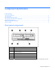
Component identification In this section Front panel components ............................................................................................................................ 6 Front panel LEDs ...................................................................................................................................... 7 SAS and SATA hard drive LEDs .................................................................................................................
Front panel LEDs Item Description Status 1 UID LED Blue = Identified Blue flashing = Active remote management Off = No active remote management 2 Health LED Green = Normal Flashing = Booting Amber = Degraded condition Red = Critical condition 3 NIC 1 LED* Green = Network linked Green flashing = Network activity Off = No link or activity 4 NIC 2 LED* Green = Network linked Green flashing = Network activity Off = No link or activity 5 System power LED Green = On Amber = Standby (auxiliary po
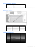
SAS and SATA hard drive LEDs Item Description 1 Fault/UID LED (amber/blue) 2 Online LED (green) SAS and SATA hard drive LED combinations Online/activity LED Fault/UID LED (green) (amber/blue) Interpretation On, off, or flashing Alternating amber and blue The drive has failed, or a predictive failure alert has been received for this drive; it also has been selected by a management application.
Online/activity LED Fault/UID LED (green) (amber/blue) Interpretation Off Steadily amber A critical fault condition has been identified for this drive, and the controller has placed it offline. Replace the drive as soon as possible. Off Amber, flashing regularly (1 Hz) A predictive failure alert has been received for this drive. Replace the drive as soon as possible. Off Off The drive is offline, a spare, or not configured as part of an array.
Mezzanine connector definitions Item PCIe Mezzanine connector 1 x4, Type I mezzanine card only Mezzanine connector 2 x8, Type 1 or II mezzanine card A PCIe x4 mezzanine connector supports x8 cards at up to x4 speeds. A PCIe x8 mezzanine connector supports x16 cards at up to x8 speeds.
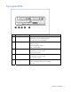
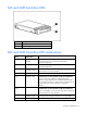
Hard drive backplane components Item Description 1 Hard drive backplane thumbscrews (5) 2 Smart Array E200i Controller cache module 3 Internal USB connector ("Internal USB functionality" on page 52) Local I/O cable Item Connector Description 1 Server blade For connecting to the local I/O cable connector on the server blade front panel 2 Video For connecting a video monitor Component identification 11
Item Connector Description 3 USB For connecting up to two USB devices 4 Serial For trained personnel to connect a null modem serial cable and perform advanced diagnostic procedures Component identification 12
Operations In this section Power up the server blade....................................................................................................................... 13 Power down the server blade .................................................................................................................. 13 Remove the server blade ......................................................................................................................... 14 Remove the access panel ..................
After initiating a virtual power down command, be sure that the server blade goes into standby mode by observing that the system power LED is amber. Remove the server blade To remove the component: 1. Identify the proper server blade. 2. Power down the server blade (on page 13). 3. Remove the server blade. 4. Place the server blade on a flat, level work surface.
Install the access panel 1. Place the access panel on top of the server blade with the hood latch open. Allow the panel to extend past the rear of the server blade approximately 0.8 cm (0.2 in). 2. Engage the anchoring pin with the corresponding hole in the latch. 3. Push down on the hood latch. The access panel slides to a closed position.
Setup In this section Overview .............................................................................................................................................. 16 Installing an HP BladeSystem c-Class enclosure .......................................................................................... 16 Installing server blade options.................................................................................................................. 16 Installing interconnect modules..............
Installing interconnect modules For specific steps to install interconnect modules, see the documentation that ships with the interconnect module. Interconnect bay numbering and device mapping To support network connections for specific signals, install an interconnect module in the bay corresponding to the embedded NIC or mezzanine signals.
Installing a server blade CAUTION: To prevent improper cooling and thermal damage, do not operate the server blade or the enclosure unless all hard drive and device bays are populated with either a component or a blank. 1. Remove the blank. 2. Remove the enclosure connector cover. 3. Prepare the server blade for installation.
4. Install the server blade. Completing the configuration To complete the server blade and HP BladeSystem configuration, see the overview card that ships with the enclosure.
Hardware options installation In this section Introduction ........................................................................................................................................... 20 Hard drive option................................................................................................................................... 20 Processor option.....................................................................................................................................
2. Prepare the hard drive. 3. Install the hard drive. 4. Determine the status of the hard drive from the hot-plug hard drive LEDs ("SAS and SATA hard drive LEDs" on page 8). Processor option WARNING: To reduce the risk of personal injury from hot surfaces, allow the drives and the internal system components to cool before touching them. CAUTION: To avoid damage to the system board: • Do not touch the processor socket contacts.
• • Handle the processor only by the edges. Do not touch the bottom of the processor, especially the contact area. CAUTION: To prevent possible server malfunction and damage to the equipment, multiprocessor configurations must contain processors with the same part number. CAUTION: To prevent possible server blade overheating, always populate processor socket 2 with a processor and a heatsink or a processor cover and a heatsink blank.
6. Remove the front panel/hard drive cage assembly. 7. Remove the heatsink blank. Retain the heatsink blank for future use.
8. Open the processor retaining latch and the processor socket retaining bracket. 9. Remove the processor socket protective cover. IMPORTANT: Be sure the processor remains inside the processor installation tool.
10. If the processor has separated from the installation tool, carefully re-insert the processor in the tool. 11. Align the processor installation tool with the socket and install the processor.
12. Press down firmly until the processor installation tool clicks and separates from the processor, and then remove the processor installation tool. 13. Close the processor socket retaining bracket and the processor retaining latch.
14. Remove the thermal interface protective cover from the heatsink. CAUTION: Heatsink retaining screws should be tightened in diagonally opposite pairs (in an "X" pattern). 15. Install the heatsink. 16. Install the front panel/hard drive cage assembly.
17. Install the hard drive backplane. Press down on the connector to seat the board. 18. Install the hard drives ("Hard drive option" on page 20). 19. Install the access panel (on page 15). 20. Install the server blade ("Installing a server blade" on page 18). Memory options This server contains eight FBDIMM slots. You can expand server memory by installing supported Registered DDR-2 FBDIMMs.
The memory subsystem for this server is divided into two branches. Each memory branch is essentially a separate memory controller. The FBDIMMs map to the two branches as indicated in the following table: Branch 0 Branch 1 FBDIMM 1A FBDIMM 5B FBDIMM 3A FBDIMM 7B FBDIMM 2C FBDIMM 6D FBDIMM 4C FBDIMM 8D This multi-branch architecture provides enhanced performance in Advanced ECC mode. The concept of multiple branches is important for the operation of online spare mode and mirrored memory mode.
In online spare mode, a single rank of memory acts as the spare memory. For single-rank FBDIMMs, the entire FBDIMM acts as the spare memory. For a dual-rank FBDIMM, only half of the FBDIMM acts as the spare memory while the other half is available for operating system and application usage. If one of the non-spare FBDIMMs receives correctable memory errors at a higher rate than a specific threshold, the server blade automatically copies the memory contents of the degraded rank to the online spare rank.
• Bank A and bank B must contain FBDIMMs with identical part numbers. If installed, bank C and bank D must also contain FBDIMMs with identical part numbers. When using mirrored memory mode, FBDIMMs must be populated as specified in the following table: Configuration Bank A Bank B Bank C Bank D 1A and 3A 5B and 7B 2C and 4C 6D and 8D 1 X X — — 2 X X X X After installing FBDIMMs, use RBSU to configure the system for mirrored memory support ("Configuring mirrored memory" on page 47).
Optional mezzanine cards enable network connectivity and provide Fibre Channel support. For mezzanine card locations, see the system board components (on page 9) . For mezzanine card mapping, see the HP ProLiant BL460c Server Blade Installation Instructions. To install the component: 1. Power down the server blade (on page 13). 2. Remove the server blade (on page 14). 3. Remove the access panel (on page 14). 4. Remove the mezzanine connector cover. 5. Install the mezzanine card.
Smart Array E200i Battery-Backed Write Cache enabler option The optional BBWC enabler provides the system with a means for storing and saving data in the event of an unexpected system shutdown. CAUTION: To prevent a server blade malfunction or damage to the equipment, do not add or remove the battery pack while an array capacity expansion, RAID level migration, or stripe size migration is in progress.
6. Remove the Smart Array E200i cache module from the cache module slot. 7. Install the Smart Array E200i battery pack on the cache module.
8. Install the Smart Array E200i cache module. 9. Install the hard drive backplane. Press down on the connector to seat the board. 10. Install the hard drives ("Hard drive option" on page 20). 11. Install the access panel (on page 15). 12. Install the server blade ("Installing a server blade" on page 18).
Cabling In this section Using the local I/O cable........................................................................................................................ 36 Connecting locally to a server blade with video and USB devices ................................................................
4. Connect a USB keyboard to the second USB connector. Item Description 1 Monitor 2 USB mouse 3 USB keyboard 4 Local I/O cable Accessing a server blade with local media devices Use the following configuration when configuring a server blade or loading software updates and patches from a USB CD/DVD-ROM or a USB diskette. 1. Connect the local I/O cable to the server blade. 2. Connect the video connector to a monitor. 3. Connect a USB hub to one USB connector. 4.
NOTE: Use a USB hub when connecting a USB diskette drive and/or USB CD-ROM drive to the server blade. The USB hub provides additional connections.
Software and configuration utilities In this section Server blade deployment tools ................................................................................................................. 39 Configuration tools ................................................................................................................................. 45 Management tools..................................................................................................................................
• Send alerts from iLO 2 regardless of the state of the host server blade. • Access advanced troubleshooting features provided by iLO 2. • Launch a web browser, use SNMP alerting, and diagnose the server blade with HP SIM. • Configure static IP bay settings for the dedicated iLO 2 management NICs on each server blade in an enclosure for faster deployment. To connect to the server blade using iLO 2, install the server blade in an enclosure.
• TCP/IP networking and an IP address compatible with one of the following: the iLO 2 Diagnostic Port IP address or an assigned DHCP or static IP address • CD-ROM drive, CD/DVD-ROM drive, and/or diskette drive • Any of the following Java™ Runtime Environment versions: 1.3.1_02 1.3.1_07 1.3.1_08 1.4.1 for Windows® users only 1.4.2 for Linux users only Access the Java™ Runtime Environment versions at the HP website (http://java.sun.com/products/archive/index.html).
IMPORTANT: To deploy a server blade without the RDP, create a bootable diskette or image of a bootable diskette. • PXE deployment (on page 42) • CD-ROM deployment (on page 42) • Diskette image deployment (on page 43) • SAN configuration (on page 44) PXE deployment PXE enables server blades to load an image over the network from a PXE server, and then execute it in memory. The first NIC on the server blade is the default PXE boot NIC, but any of the other NC series NICs can be configured to boot PXE.
iLO virtual CD-ROM To deploy with a boot CD: 1. Do one of the following: • Insert the boot CD into the client PC that is using the iLO 2 Remote Console. • Use iLO 2 to create an image file of the boot CD. • Copy the image of the boot CD to a location on the network or the client PC hard drive. 2. Remotely access the server blade through iLO 2. Refer to "HP BladeSystem c-Class advanced management (on page 39)." 3. Click the Virtual Devices tab. 4. Select Virtual Media. 5.
• PXE ("PXE deployment" on page 42) Creating a boot diskette The SmartStart Scripting Toolkit provides the tools and information for creating a boot diskette. For details, refer to the SmartStart Scripting Toolkit User Guide and download the latest version of the software from the HP website (http://www.hp.com/servers/sstoolkit). As an alternative method, configure the hardware manually with RBSU and the iLO 2 remote console.
Configuration tools SmartStart software SmartStart is a collection of software that optimizes single-server setup, providing a simple and consistent way to deploy server configuration. SmartStart has been tested on many ProLiant server products, resulting in proven, reliable configurations.
Using RBSU The first time you power up the server blade, the system prompts you to enter RBSU and select a language. Default configuration settings are made at this time and can be changed later. Most of the features in RBSU are not required to set up the server blade. To navigate RBSU, use the following keys: • To access RBSU, press the F9 key during power up when prompted in the upper right corner of the screen. • To navigate the menu system, use the arrow keys.
BIOS Serial Console BIOS Serial Console allows you to configure the serial port to view POST error messages and run RBSU remotely through a serial connection to the server COM port. The server that you are remotely configuring does not require a keyboard and mouse. For more information about BIOS Serial Console, refer to the BIOS Serial Console User Guide on the Documentation CD or the HP website (http://www.hp.com/servers/smartstart). Configuring mirrored memory To configure mirrored memory: 1.
• Remains available any time that the server is on • Displays on-screen tips for individual steps of a configuration procedure For optimum performance, the minimum display settings are 800 × 600 resolution and 256 colors. Servers running Microsoft® operating systems require Internet Explorer 5.5 (with Service Pack 1) or later. For Linux servers, refer to the README.TXT file for additional browser and support information.
8. Press the Esc key to close the menu. 9. Press the Esc key to exit RBSU. 10. Press the F10 key to confirm exiting RBSU. The server will automatically reboot. Management tools Automatic Server Recovery ASR is a feature that causes the system to restart when a catastrophic operating system error occurs, such as a blue screen, ABEND, or panic. A system fail-safe timer, the ASR timer, starts when the System Management driver, also known as the Health Driver, is loaded.
Run the Erase Utility if you must erase the system for the following reasons: • You want to install a new operating system on a server with an existing operating system. • You encounter an error when completing the steps of a factory-installed operating system installation. The Erase Utility can be accessed from the Maintenance Utilities menu of the SmartStart CD ("SmartStart software" on page 45).
HP ProLiant Essentials Server Migration Pack - Physical to ProLiant Edition The HP ProLiant Essentials Server Migration Pack – Physical to ProLiant Edition (SMP – P2P) software enables you to upgrade or replace your existing server. SMP – P2P provides an automated, accurate and affordable way to migrate existing servers and their content to the latest server technologies.
Legacy USB support provides USB functionality in environments where USB support is normally not available. Specifically, HP provides legacy USB functionality for: • POST • RBSU • Diagnostics • DOS • Operating environments which do not provide native USB support For more information on ProLiant USB support, refer to the HP website (http://h18004.www1.hp.com/products/servers/platforms/usb-support.html).
Integrated Management Log The IML records hundreds of events and stores them in an easy-to-view form. The IML timestamps each event with 1-minute granularity.
Open Services Event Manager OSEM is a standalone tool that performs real-time reactive and proactive service event filtering, analysis, and notification. The tool gathers event data from SNMP traps or information provided over an HTTP interface and notifies an administrator or HP through SMTP and ISEE. For more information, refer to the HP website (http://h18000.www1.hp.com/support/svctools/).
• Supports Microsoft® Windows NT®, Windows® 2000, Windows Server™ 2003, Novell Netware, and Linux operating systems IMPORTANT: This utility supports operating systems that may not be supported by the server. For operating systems supported by the server, refer to the HP website (http://www.hp.com/go/supportos).
Troubleshooting In this section Troubleshooting resources ....................................................................................................................... 56 Pre-diagnostic steps ................................................................................................................................ 56 Service notifications................................................................................................................................ 59 Loose connections .......
Important safety information Familiarize yourself with the safety information in the following sections before troubleshooting the server. Important safety information Before servicing this product, read the Important Safety Information document provided with the server. Symbols on equipment The following symbols may be placed on equipment to indicate the presence of potentially hazardous conditions. This symbol indicates the presence of hazardous energy circuits or electric shock hazards.
subassembly/module-level repair. Because of the complexity of the individual boards and subassemblies, no one should attempt to make repairs at the component level or to make modifications to any printed wiring board. Improper repairs can create a safety hazard. WARNING: To reduce the risk of personal injury or damage to the equipment, be sure that: • The leveling feet are extended to the floor. • The full weight of the rack rests on the leveling feet.
NOTE: To verify the server configuration, connect to the System Management homepage and select Version Control Agent. The VCA gives you a list of names and versions of all installed HP drivers, Management Agents, and utilities, and whether they are up to date. • HP recommends you have access to the server documentation for server-specific information. • HP recommends you have access to the SmartStart CD for value-added software and drivers required during the troubleshooting process.
Start diagnosis flowchart Use the following flowchart to start the diagnostic process.
General diagnosis flowchart The General diagnosis flowchart provides a generic approach to troubleshooting. If you are unsure of the problem, or if the other flowcharts do not fix the problem, use the following flowchart. Item See 1 "Symptom information (on page 58)" 2 "Loose connections (on page 59)" 3 "Service notifications (on page 59)" 4 The most recent version of a particular server or option firmware is available on the following websites: • HP Support website (http://www.hp.
Server blade power-on problems flowchart Symptoms: • The server does not power on. • The system power LED is off or amber. • The health LED is red or amber.
NOTE: For the location of server LEDs and information on their statuses, refer to the server documentation. Possible causes: • Improperly seated or faulty power supply • Loose or faulty power cord • Power source problem • Power on circuit problem • Improperly seated component or interlock problem • Faulty internal component Item See 1 "Component identification (on page 6)" 2 Maintenance and service guides for c-Class server blades, located on the HP website (http://www.hp.
POST problems flowchart Symptoms: • Server does not complete POST NOTE: The server has completed POST when the system attempts to access the boot device.
OS boot problems flowchart There are two ways to use SmartStart when diagnosing OS boot problems on a server blade: • Use iLO to remotely attach virtual devices to mount the SmartStart CD onto the server blade. • Use a local I/O cable and drive to connect to the server blade, and then restart the server blade.
Possible causes: • Corrupted OS • Hard drive subsystem problem • Incorrect boot order setting in RBSU Item See 1 HP ROM-Based Setup Utility User Guide (http://www.hp.com/servers/smartstart) 2 "POST problems flowchart (on page 64)" 3 • "Hard drive problems" in the HP ProLiant Servers Troubleshooting Guide located on the Documentation CD or on the HP website (http://www.hp.
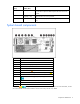
* See the server blade OS boot problems flowchart (on page 65) Server fault indications flowchart Symptoms: • Server boots, but a fault event is reported by Insight Management Agents (on page 50) • Server boots, but the internal health LED, external health LED, or component health LED is red or amber NOTE: For the location of server LEDs and information on their statuses, refer to the server documentation.
Possible causes: • Improperly seated or faulty internal or external component • Unsupported component installed • Redundancy failure • System overtemperature condition Item See 1 "Management agents (on page 50)" or in the HP ProLiant Servers Troubleshooting Guide located on the Documentation CD or on the HP website (http://www.hp.com/support) 2 • "Integrated Management Log" or in the HP ProLiant Servers Troubleshooting Guide located on the Documentation CD or on the HP website (http://www.hp.
POST error messages and beep codes For a complete listing of error messages, refer to the "POST error messages" in the HP ProLiant Servers Troubleshooting Guide located on the Documentation CD or on the HP website (http://www.hp.com/support). WARNING: To avoid potential problems, ALWAYS read the warnings and cautionary information in the server documentation before removing, replacing, reseating, or modifying system components.
Battery replacement If the server blade no longer automatically displays the correct date and time, you may need to replace the battery that provides power to the real-time clock. Under normal use, battery life is 5 to 10 years. WARNING: The computer contains an internal lithium manganese dioxide, a vanadium pentoxide, or an alkaline battery pack. A risk of fire and burns exists if the battery pack is not properly handled. To reduce the risk of personal injury: • Do not attempt to recharge the battery.
6. Remove the front panel/hard drive cage assembly. 7. Remove the system board. 8. Identify the battery location ("System board components" on page 9).
9. Remove the battery. IMPORTANT: Replacing the system board battery resets the system ROM to its default configuration. After replacing the battery, reconfigure the system through RBSU. To replace the component, reverse the removal procedure. For more information about battery replacement or proper disposal, contact an authorized reseller or an authorized service provider.
Regulatory compliance notices In this section Regulatory compliance identification numbers ........................................................................................... 73 Federal Communications Commission notice ............................................................................................. 73 Declaration of conformity for products marked with the FCC logo, United States only..................................... 74 Modifications...................................................
Class A equipment This equipment has been tested and found to comply with the limits for a Class A digital device, pursuant to Part 15 of the FCC Rules. These limits are designed to provide reasonable protection against harmful interference when the equipment is operated in a commercial environment. This equipment generates, uses, and can radiate radio frequency energy and, if not installed and used in accordance with the instructions, may cause harmful interference to radio communications.
Modifications The FCC requires the user to be notified that any changes or modifications made to this device that are not expressly approved by Hewlett-Packard Company may void the user’s authority to operate the equipment. Cables Connections to this device must be made with shielded cables with metallic RFI/EMI connector hoods in order to maintain compliance with FCC Rules and Regulations.
Disposal of waste equipment by users in private households in the European Union This symbol on the product or on its packaging indicates that this product must not be disposed of with your other household waste. Instead, it is your responsibility to dispose of your waste equipment by handing it over to a designated collection point for the recycling of waste electrical and electronic equipment.
Korean notice Class A equipment Class B equipment Laser compliance This product may be provided with an optical storage device (that is, CD or DVD drive) and/or fiber optic transceiver. Each of these devices contains a laser that is classified as a Class 1 Laser Product in accordance with US FDA regulations and the IEC 60825-1. The product does not emit hazardous laser radiation. Each laser product complies with 21 CFR 1040.10 and 1040.11 except for deviations pursuant to Laser Notice No.
• • • Do not attempt to recharge the battery. Do not expose the battery to temperatures higher than 60°C (140°F). Do not disassemble, crush, puncture, short external contacts, or dispose of in fire or water. Batteries, battery packs, and accumulators should not be disposed of together with the general household waste. To forward them to recycling or proper disposal, please use the public collection system or return them to HP, an authorized HP Partner, or their agents.
Electrostatic discharge In this section Preventing electrostatic discharge............................................................................................................. 79 Grounding methods to prevent electrostatic discharge ................................................................................ 79 Preventing electrostatic discharge To prevent damaging the system, be aware of the precautions you need to follow when setting up the system or handling parts.
Specifications In this section Environmental specifications .................................................................................................................... 80 Server blade specifications......................................................................................................................
Technical support In this section Before you contact HP............................................................................................................................. 81 HP contact information............................................................................................................................ 81 Customer Self Repair ..............................................................................................................................
• Mandatory—Parts for which customer self repair is mandatory. If you request HP to replace these parts, you will be charged for the travel and labor costs of this service. • Optional—Parts for which customer self repair is optional. These parts are also designed for customer self repair. If, however, you require that HP replace them for you, there may or may not be additional charges, depending on the type of warranty service designated for your product.
Pour plus d'informations sur le programme CSR de HP, contactez votre Mainteneur Agrée local. Pour plus d'informations sur ce programme en Amérique du Nord, consultez le site Web HP (http://www.hp.com/go/selfrepair). Riparazione da parte del cliente Per abbreviare i tempi di riparazione e garantire una maggiore flessibilità nella sostituzione di parti difettose, i prodotti HP sono realizzati con numerosi componenti che possono essere riparati direttamente dal cliente (CSR, Customer Self Repair).
CSR-Teile werden abhängig von der Verfügbarkeit und vom Lieferziel am folgenden Geschäftstag geliefert. Für bestimmte Standorte ist eine Lieferung am selben Tag oder innerhalb von vier Stunden gegen einen Aufpreis verfügbar. Wenn Sie Hilfe benötigen, können Sie das HP technische Support Center anrufen und sich von einem Mitarbeiter per Telefon helfen lassen. Den Materialien, die mit einem CSRErsatzteil geliefert werden, können Sie entnehmen, ob das defekte Teil an HP zurückgeschickt werden muss.
Customer Self Repair Veel onderdelen in HP producten zijn door de klant zelf te repareren, waardoor de reparatieduur tot een minimum beperkt kan blijven en de flexibiliteit in het vervangen van defecte onderdelen groter is. Deze onderdelen worden CSR-onderdelen (Customer Self Repair) genoemd.
Conforme a disponibilidade e o local geográfico, as peças CSR serão enviadas no primeiro dia útil após o pedido. Onde as condições geográficas permitirem, a entrega no mesmo dia ou em quatro horas pode ser feita mediante uma taxa adicional. Se precisar de auxílio, entre em contato com o Centro de suporte técnico da HP para que um técnico o ajude por telefone. A HP especifica nos materiais fornecidos com a peça CSR de reposição se a peça com defeito deve ser devolvida à HP.
Technical support 87
Technical support 88
Acronyms and abbreviations ABEND abnormal end ACU Array Configuration Utility ADU Array Diagnostics Utility AMP Advanced Memory Protection ASR Automatic Server Recovery BBWC battery-backed write cache FBDIMM fully buffered DIMM FC Fibre Channel iLO 2 Integrated Lights-Out 2 IML Integrated Management Log ORCA Option ROM Configuration for Arrays POST Power-On Self Test Acronyms and abbreviations 89
RBSU ROM-Based Setup Utility RILOE Remote Insight Lights-Out Edition SAS serial attached SCSI SATA serial ATA SIM Systems Insight Manager UID unit identification USB universal serial bus VCA Version Control Agent VCRM Version Control Repository Manager Acronyms and abbreviations 90
Index A access panel 14, 15 ACU (Array Configuration Utility) 47 ADU (Array Diagnostic Utility) 53 Altiris Deployment Solution 48 Altiris eXpress Deployment Server 48 array configuration 47 Array Configuration Utility (ACU) 47 Array Diagnostic Utility (ADU) 53 ASR (Automatic Server Recovery) 49, 89 authorized reseller 81 auto-configuration process 46 Automatic Server Recovery (ASR) 49, 89 Autorun menu 45 B backplane, hard drive 11 batteries, replacing 70, 77 battery 9, 70, 77 battery replacement notice 77
hard drive bays 6 hard drive LEDs 8 hard drives 8, 20 hard drives, installing 20 hardware options 20 hardware options installation 20 health driver 49 health LEDs 7, 8 heatsink 21 heatsink blank 21 HP Insight Diagnostics 52 HP ProLiant Essentials Foundation Pack 50 HP ProLiant Essentials Rapid Deployment Pack 48 HP Systems Insight Manager, overview 50 HP Technical Support 81 loose connections 59 M Management Agents 50 management tools 39, 49 memory 10, 28, 31 memory, mirrored 30, 47 memory, online spare 2
resources, troubleshooting 56 ROM redundancy 51 ROM, updating 54 ROM-Based Setup Utility (RBSU) 45 ROMPaq utility 49, 51 S safety considerations 57 safety information 51 SAS drives 8 SAS hard drive LEDs 8 SATA hard drive 8 SATA hard drive LEDs 8 scripted installation 45 serial connector 11 serial label pull tab 6 serial number 48 series number 73 server blade handle 6 server fault indications flowchart 67 server features and options 20 service notifications 59 SmartStart autorun menu 45 SmartStart Scriptin