HP ProLiant BL490c G7 Server Blade Maintenance and Service Guide Abstract This guide describes identification and maintenance procedures, diagnostic tools, specifications and requirements for hardware components and software. This guide is for an experienced service technician. HP assumes you are qualified in the servicing of computer equipment, trained in recognizing hazards in products, and are familiar with weight and stability precautions.
© Copyright 2010, 2011 Hewlett-Packard Development Company, L.P. The information contained herein is subject to change without notice. The only warranties for HP products and services are set forth in the express warranty statements accompanying such products and services. Nothing herein should be construed as constituting an additional warranty. HP shall not be liable for technical or editorial errors or omissions contained herein. Microsoft and Windows are U.S.
Contents Customer self repair ...................................................................................................................... 5 Parts only warranty service ......................................................................................................................... 5 Illustrated parts catalog ............................................................................................................... 16 Server blade components ...........................................
System board components ........................................................................................................................ 55 Mezzanine connector definitions ..................................................................................................... 56 System maintenance switch ............................................................................................................. 56 System maintenance switch procedures ...................................................
Customer self repair HP products are designed with many Customer Self Repair (CSR) parts to minimize repair time and allow for greater flexibility in performing defective parts replacement. If during the diagnosis period HP (or HP service providers or service partners) identifies that the repair can be accomplished by the use of a CSR part, HP will ship that part directly to you for replacement. There are two categories of CSR parts: • Mandatory—Parts for which customer self repair is mandatory.
Obligatoire - Pièces pour lesquelles la réparation par le client est obligatoire. Si vous demandez à HP de remplacer ces pièces, les coûts de déplacement et main d'œuvre du service vous seront facturés. Facultatif - Pièces pour lesquelles la réparation par le client est facultative. Ces pièces sont également conçues pour permettre au client d'effectuer lui-même la réparation.
In base alla disponibilità e alla località geografica, le parti CSR vengono spedite con consegna entro il giorno lavorativo seguente. La consegna nel giorno stesso o entro quattro ore è offerta con un supplemento di costo solo in alcune zone. In caso di necessità si può richiedere l'assistenza telefonica di un addetto del centro di supporto tecnico HP. Nel materiale fornito con una parte di ricambio CSR, HP specifica se il cliente deve restituire dei componenti.
defekte Teil nicht zurückschicken, kann HP Ihnen das Ersatzteil in Rechnung stellen. Im Falle von Customer Self Repair kommt HP für alle Kosten für die Lieferung und Rücksendung auf und bestimmt den Kurier-/Frachtdienst. Weitere Informationen über das HP Customer Self Repair Programm erhalten Sie von Ihrem Servicepartner vor Ort. Informationen über das CSR-Programm in Nordamerika finden Sie auf der HP Website unter (http://www.hp.com/go/selfrepair).
enviara el componente defectuoso requerido, HP podrá cobrarle por el de sustitución. En el caso de todas sustituciones que lleve a cabo el cliente, HP se hará cargo de todos los gastos de envío y devolución de componentes y escogerá la empresa de transporte que se utilice para dicho servicio. Para obtener más información acerca del programa de Reparaciones del propio cliente de HP, póngase en contacto con su proveedor de servicios local.
Neem contact op met een Service Partner voor meer informatie over het Customer Self Repair programma van HP. Informatie over Service Partners vindt u op de HP website (http://www.hp.com/go/selfrepair). Garantieservice "Parts Only" Het is mogelijk dat de HP garantie alleen de garantieservice "Parts Only" omvat. Volgens de bepalingen van de Parts Only garantieservice zal HP kosteloos vervangende onderdelen ter beschikking stellen.
No caso desse serviço, a substituição de peças CSR é obrigatória. Se desejar que a HP substitua essas peças, serão cobradas as despesas de transporte e mão-de-obra do serviço.
Customer self repair 12
Customer self repair 13
Customer self repair 14
Customer self repair 15
Illustrated parts catalog Server blade components Item Description Spare part number Customer self repair (on page 5) 1 Access panel 619322-001 Mandatory1 2 Hardware and plastics kit 619321-001 Mandatory1 a) Heatsink blank — — b) DIMM baffle with T-15 Torx screwdriver — — c) Battery tray — — d) Front bezel — — e) System connector cover* — — Illustrated parts catalog 16
Item Description Spare part number Customer self repair (on page 5) 3 Processors — — a) 2.13-GHz Intel® Xeon® processor L5630** 594851-001 Optional2 b) 2.26-GHz Intel® Xeon® processor L5640* ** 594890-001 Optional2 c) 2.66-GHz Intel® Xeon® processor X5650* ** 594884-001 Optional2 d) 2.93-GHz Intel® Xeon® processor X5670* ** 594882-001 Optional2 e) 3.06-GHz Intel® Xeon® processor X5675* ** 638134-001 Optional2 f) 3.20-GHz Intel® Xeon® processor X5672* ** 638135-001 Optional2 g) 2.
Item 9 10 Description Spare part number Customer self repair (on page 5) g) P-series battery, 650 mAh* 462976-001 Mandatory1 h) P-series cache module, 256 MB* 462974-001 Mandatory1 Ethernet Mezzanine adapters — — a) HP NC325m PCI Express Quad Port Gigabit Server Adapter for 436011-001 c-Class BladeSystem* Mandatory1 b) HP NC364m Quad Port 1GbE BL-c Adapter* 448066-001 Mandatory1 c) HP NC382m Dual Port 1GbE Multifunction BL-c Adapter* 462748-001 Mandatory1 d) HP BLc QLogic iSCSI Dual P
Item Description Spare part number Customer self repair (on page 5) 15 HP c-Class Blade SUV Cable* 416003-001 Mandatory1 16 System battery* 234556-001 Mandatory1 17 USB/SD card module* 534756-001 Mandatory1 18 Trusted Platform Module* 505836-001 No³ *Not shown **Do not mix processors with different model numbers, speeds, cache sizes, or power consumption. 1 Mandatory—Parts for which customer self repair is mandatory.
Mandatory: Verplicht—Onderdelen waarvoor Customer Self Repair verplicht is. Als u HP verzoekt deze onderdelen te vervangen, komen de reiskosten en het arbeidsloon voor uw rekening. 2 Optional: Optioneel—Onderdelen waarvoor reparatie door de klant optioneel is. Ook deze onderdelen zijn ontworpen voor reparatie door de klant. Als u echter HP verzoekt deze onderdelen voor u te vervangen, kunnen daarvoor extra kosten in rekening worden gebracht, afhankelijk van het type garantieservice voor het product.
Removal and replacement procedures Required tools You need the following items for some procedures: • T-15 Torx screwdriver (provided inside the access panel) • Flathead screwdriver • HP Insight Diagnostics software ("HP Insight Diagnostics" on page 51) Safety considerations Before performing service procedures, review all the safety information.
Symbols on equipment The following symbols may be placed on equipment to indicate the presence of potentially hazardous conditions. This symbol indicates the presence of hazardous energy circuits or electric shock hazards. Refer all servicing to qualified personnel. WARNING: To reduce the risk of injury from electric shock hazards, do not open this enclosure. Refer all maintenance, upgrades, and servicing to qualified personnel. This symbol indicates the presence of electric shock hazards.
• Press and release the Power On/Standby button. This method initiates a controlled shutdown of applications and the OS before the server blade enters standby mode. • Press and hold the Power On/Standby button for more than 4 seconds to force the server blade to enter standby mode. This method forces the server blade to enter standby mode without properly exiting applications and the OS. It provides an emergency shutdown method if an application stops responding.
3. Remove the server blade. 4. Place the server blade on a flat, level work surface. WARNING: To reduce the risk of personal injury from hot surfaces, allow the drives and the internal system components to cool before touching them. CAUTION: To prevent damage to electrical components, properly ground the server blade before beginning any installation procedure. Improper grounding can cause ESD. Access panel To remove the component: 1. Power down the server blade (on page 22). 2.
5. Disconnect the hard drive cables. 6. Remove the hard drive. To replace the component, reverse the removal procedure. DIMM baffle To remove the component: 1. Power down the server blade (on page 22). 2. Remove the server blade (on page 23). 3. Remove the access panel ("Access panel" on page 24).
4. Disconnect the hard drive cables. 5. Remove the DIMM baffle. 6. Remove the hard drive ("Hard drive" on page 24). To replace the component, reverse the removal procedure. DIMMs To remove the component: 1. Power down the server blade (on page 22). 2. Remove the server blade (on page 23). 3. Remove the access panel ("Access panel" on page 24). 4. Disconnect the hard drive cables from the system board. 5. Remove the DIMM baffle ("DIMM baffle" on page 25).
For this procedure, removing the hard drive from the DIMM baffle is not required. 6. Remove the DIMM. To replace the component, reverse the removal procedure. Mezzanine card Optional mezzanine cards enable network connectivity and provide Fibre Channel support. For mezzanine card locations, see the system board components (on page 55). To remove the component: 1. Power down the server blade (on page 22). 2. Remove the server blade (on page 23). 3. Remove the access panel ("Access panel" on page 24).
To replace the component: 1. Install the mezzanine card. Press down above the back side of the connector to seat the card. 2. Install the access panel ("Access panel" on page 24). 3. Install the server blade. Front bezel To remove the component: WARNING: To reduce the risk of personal injury from hot surfaces, allow the drives and the internal system components to cool before touching them. 1. Power down the server blade (on page 22). 2. Remove the server blade (on page 23). 3.
To replace the component, reverse the removal procedure. Battery tray To remove the component: 1. Power down the server blade (on page 22). 2. Remove the server blade (on page 23). 3. Remove the access panel ("Access panel" on page 24). 4. Remove the battery tray. To replace the component, reverse the removal procedure. USB/SD card module To remove the component: 1. Power down the server blade (on page 22). 2. Remove the server blade (on page 23). 3.
5. Remove the USB/SD card module. To replace the component, reverse the removal procedure. Server blade release lever To remove the component: 1. Power down the server blade (on page 22). 2. Remove the server blade (on page 23). 3. Remove the access panel ("Access panel" on page 24). 4. Remove the front bezel ("Front bezel" on page 28). 5. Remove the server blade release lever. To replace the component, reverse the removal procedure.
Release button To remove the component: 1. Power down the server blade (on page 22). 2. Remove the server blade (on page 23). 3. Remove the access panel ("Access panel" on page 24). 4. Remove the front bezel ("Front bezel" on page 28). 5. Open the server blade release lever. 6. Remove the release button. To replace the component, reverse the removal procedure. Heatsink blank To remove the component: 1. Power down the server blade (on page 22). 2. Remove the server blade (on page 23). 3.
6. Remove the heatsink blank. To replace the component, reverse the removal procedure. Heatsink WARNING: To reduce the risk of personal injury from hot surfaces, allow the drives and the internal system components to cool before touching them. To remove the component: 1. Power down the server blade (on page 22). 2. Remove the server blade (on page 23). 3. Remove the access panel ("Access panel" on page 24). 4. Disconnect the hard drive cables. 5.
6. Remove the heatsink. To replace the component: 1. Clean the old thermal grease from the processor with the alcohol swab. Allow the alcohol to evaporate before continuing. CAUTION: The heatsink thermal interface media is not reusable and must be replaced if the heatsink is removed from the processor after it has been installed. 2. Remove the thermal interface media protective cover. CAUTION: To avoid damage to the system board, processor socket, and screws, do not overtighten the heatsink screws.
3. Install the heatsink. Insert both screws, and then alternate tightening until the heatsink is seated properly. 4. Install the DIMM baffle ("DIMM baffle" on page 25). 5. Connect the hard drive cables ("Hard drive cabling" on page 59). 6. Install the access panel ("Access panel" on page 24). 7. Install the server blade. Processor WARNING: To reduce the risk of personal injury from hot surfaces, allow the drives and the internal system components to cool before touching them.
4. Disconnect the hard drive cables. 5. Remove the DIMM baffle ("DIMM baffle" on page 25). 6. Remove the heatsink ("Heatsink" on page 32). 7. Open the processor locking lever and the processor socket retaining bracket. 8. Using the processor tool, remove the processor from the system board: a. Line up the processor tool, ensuring the locking lever graphic on the tool is oriented correctly. b. Press in on the plastic tabs, and then place the tool on the processor.
c. 9. Release the tabs, and then carefully lift the processor and tool straight up. Carefully rotate the tool, and then push in and release the tabs to secure the processor in the tool. CAUTION: To avoid damage to the processor, do not touch the bottom of the processor, especially the contact area. To replace the component: CAUTION: To avoid damage to the system board, processor socket, and screws, do not overtighten the heatsink screws.
1. Carefully insert the processor into the processor installation tool. Handle the processor by the edges only, and do not touch the bottom of the processor, especially the contact area.
2. Be sure the tool is oriented correctly. Align the processor installation tool with the socket, and then install the processor. THE PINS ON THE SYSTEM BOARD ARE VERY FRAGILE AND EASILY DAMAGED. CAUTION: THE PINS ON THE SYSTEM BOARD ARE VERY FRAGILE AND EASILY DAMAGED. To avoid damage to the system board: • Never install or remove a processor without using the processor installation tool. • Do not touch the processor socket contacts.
3. Press and hold the tabs on the processor installation tool to separate it from the processor, and then remove the tool. 4. Close the processor socket retaining bracket and the processor locking lever. CAUTION: Be sure to close the processor socket retaining bracket before closing the processor locking lever. The lever should close without resistance. Forcing the lever closed can damage the processor and socket, requiring system board replacement. 5.
6. Apply all the grease to the top of the processor in the following pattern to ensure even distribution. CAUTION: To avoid possible thermal damage, install replacement heatsinks as indicated on the heatsink labels. The heatsinks are not interchangeable between processor 1 and processor 2 within a server blade. 7. Install the heatsink. Insert both screws, and then alternate tightening until the heatsink is seated properly. 8. Install the DIMM baffle ("DIMM baffle" on page 25). 9.
6. Remove all DIMMs ("DIMMs" on page 26). 7. Remove all mezzanine cards ("Mezzanine card" on page 27). 8. Remove the USB/SD card module ("USB/SD card module" on page 29). 9. Remove the battery tray ("Battery tray" on page 29). 10. Remove the heatsink ("Heatsink" on page 32). 11. Open the processor locking lever and the processor socket retaining bracket. 12. Using the processor tool, remove the processor from the system board: a.
13. Carefully rotate the tool, and then push in and release the tabs to secure the processor in the tool. CAUTION: To avoid damage to the processor, do not touch the bottom of the processor, especially the contact area. 14. Remove the system board assembly.
1. Install the spare system board assembly. CAUTION: Failure to completely open the processor locking lever prevents the processor from seating during installation, leading to hardware damage. 2. Open the processor locking lever and the processor socket retaining bracket. Do not remove the processor socket cover. IMPORTANT: Be sure the processor remains inside the processor installation tool.
3. If the processor has separated from the installation tool, carefully re-insert the processor in the tool. Handle the processor by the edges only, and do not touch the bottom of the processor, especially the contact area.
4. Align the processor installation tool with the socket, and then install the processor. THE PINS ON THE SYSTEM BOARD ARE VERY FRAGILE AND EASILY DAMAGED. CAUTION: THE PINS ON THE SYSTEM BOARD ARE VERY FRAGILE AND EASILY DAMAGED. To avoid damage to the system board: • Never install or remove a processor without using the processor installation tool. • Do not touch the processor socket contacts. • Do not tilt or slide the processor when lowering the processor into the socket.
5. Press the tabs on the processor installation tool to separate it from the processor, and then remove the tool. 6. Close the processor socket retaining bracket and the processor locking lever. The processor socket cover is automatically ejected. Remove the cover. CAUTION: Be sure to close the processor socket retaining bracket before closing the processor locking lever. The lever should close without resistance.
9. Apply all the grease to the top of the processor in the following pattern to ensure even distribution. 10. Install the heatsink ("Heatsink" on page 32). IMPORTANT: Install all components with the same configuration that was used on the failed system board. 11. Install all components removed from the failed system board. 12. Install the access panel ("Access panel" on page 24). 13. Install the server blade.
System battery If the server blade no longer automatically displays the correct date and time, you may need to replace the battery that provides power to the real-time clock. Under normal use, battery life is 5 to 10 years. WARNING: The computer contains an internal lithium manganese dioxide, a vanadium pentoxide, or an alkaline battery pack. A risk of fire and burns exists if the battery pack is not properly handled. To reduce the risk of personal injury: • • • • Do not attempt to recharge the battery.
CAUTION: Any attempt to remove an installed TPM from the system board breaks or disfigures the TPM security rivet. Upon locating a broken or disfigured rivet on an installed TPM, administrators should consider the system compromised and take appropriate measures to ensure the integrity of the system data. If you suspect a TPM board failure, leave the TPM installed and remove the system board. Contact an HP authorized service provider for a replacement system board and TPM board.
Diagnostic tools Troubleshooting resources The HP ProLiant Servers Troubleshooting Guide provides procedures for resolving common problems and comprehensive courses of action for fault isolation and identification, error message interpretation, issue resolution, and software maintenance on ProLiant servers and server blades. This guide includes problem-specific flowcharts to help you navigate complex troubleshooting processes. To view the guide, select a language: • English (http://www.hp.
HP Insight Diagnostics HP Insight Diagnostics is a proactive server blade management tool, available in both offline and online versions, that provides diagnostics and troubleshooting capabilities to assist IT administrators who verify server blade installations, troubleshoot problems, and perform repair validation. HP Insight Diagnostics Offline Edition performs various in-depth system and component testing while the OS is not running. To run this utility, launch the SmartStart CD.
HP Insight Remote Support software HP strongly recommends that you install HP Insight Remote Support software to complete the installation or upgrade of your product and to enable enhanced delivery of your HP Warranty, HP Care Pack Service, or HP contractual support agreement.
External USB functionality HP provides external USB support to enable local connection of USB devices for server blade administration, configuration, and diagnostic procedures. For more information, see "Using the HP c-Class Blade SUV Cable (on page 59)." For additional security, external USB functionality can be disabled through RBSU. Disabling external USB support in RBSU disables the USB connectors on the HP c-Class Blade SUV Cable.
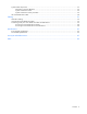
Component identification Front panel components Item Description 1 HP c-Class Blade SUV Cable connector 2 Serial label pull tab 3 Release button 4 Power On/Standby button 5 Server blade release lever Front panel LEDs Item Description Status 1 UID LED Blue = Identified Blue flashing = Active remote management Off = No active remote management Component identification 54
Item Description Status 2 Internal health LED Green = Normal Flashing = Booting Amber = Degraded condition Red = Critical condition 3 Flex 1 LED Green = Network linked Green flashing = Network activity Off = No link or activity 4 Flex 2 LED Green = Network linked Green flashing = Network activity Off = No link or activity 5 Hard drive activity LED Green = Activity Off = No activity 6 System power LED Green = On Amber = Standby (auxiliary power available) Off = Off System board components
Item Description 13 TPM connector 14 System maintenance switch 15 Processor socket 2 16 Processor socket 1 The symbols correspond to the symbols located on the interconnect bays. For more information, see the HP ProLiant BL490c G7 Server Blade Installation Instructions that ship with the server blade.
5. Install the access panel ("Access panel" on page 24). 6. Install the server blade in the enclosure and power up the server blade. 7. Wait for the POST message that prompts you to change the switch setting: Maintenance switch detected in the "On" position. Power off the server and turn switch to the "Off" position. 8. Repeat steps 1 through 3. 9. Change position 6 of the system maintenance switch to off. 10. Repeat steps 5 and 6.
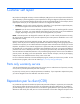
HP c-Class Blade SUV Cable Item Connector Description 1 Server blade For connecting to the SUV connector on the server blade front panel 2 Video For connecting a video monitor 3 USB For connecting up to two USB devices 4 Serial For trained personnel to connect a null modem serial cable and perform advanced diagnostic procedures Component identification 58
Cabling Hard drive cabling CAUTION: When routing cables, always be sure that the cables are not in a position where they can be pinched or crimped. Using the HP c-Class Blade SUV Cable The HP c-Class Blade SUV Cable enables the user to perform server blade administration, configuration, and diagnostic procedures by connecting video and USB devices directly to the server blade. For SUV cable connectors, see "HP c-Class Blade SUV Cable (on page 58).
Numerous configurations are possible. This section offers two possible configurations. For more information, see "USB support and functionality (on page 52)." Accessing a server blade with local KVM For this configuration, a USB hub is not necessary. To connect additional devices, use a USB hub. CAUTION: Before disconnecting the SUV cable from the connector, always squeeze the release buttons on the sides of the connector. Failure to do so can result in damage to the equipment. 1.
3. Connect a USB hub to one USB connector. 4.
Specifications Environmental specifications Specification Value — Temperature range* Operating 10°C to 35°C (50°F to 95°F) Non-operating -30°C to 60°C (-22°F to 140°F) Relative humidity (noncondensing)** — Operating 10% to 90% @ 28°C (82.4°F) Non-operating 5% to 95% @ 38.7°C (101.7°F) Altitude† — Operating 3050 m (10,000 ft) Non-operating 9144 m (30,000 ft) * The following temperature conditions and limitations apply: - All temperature ratings shown are for sea level.
Acronyms and abbreviations CSR Customer Self Repair HP SIM HP Systems Insight Manager iLO 3 Integrated Lights-Out 3 IML Integrated Management Log POST Power-On Self Test PSP ProLiant Support Pack RBSU ROM-Based Setup Utility SMP Server Migration Pack SUV serial, USB, video UID unit identification USB universal serial bus Acronyms and abbreviations 63
Index A access panel 24 additional information 50 B baffles 25 batteries, replacing 48 battery 48 battery tray 29, 55 buttons 54 C cables 59 cabling 59 cabling, hard drive 59 components 16, 21, 48, 54, 55 components, front panel 54 components, identification 54, 55 connectors 54, 56 CSR (customer self repair) 5 customer self repair (CSR) 5 D diagnostic tools 50, 51 diagnostics utility 51 DIMM baffles 25 DIMM slots 55 DIMMs 26, 55 E electrostatic discharge 21 enclosure connector 55 environmental specific
P T part numbers 16 Power On/Standby button 54, 55 powering down 22 preparation procedures 22 processor socket 55 processor tool 34, 40 processors 34 T-15 Torx screwdriver 21 tool, processor 34, 40 tools 21, 50 Torx screwdriver 21 TPM (Trusted Platform Module) 48 TPM connector 55 troubleshooting 50 troubleshooting resources 50 Trusted Platform Module (TPM) 48 R RBSU (ROM-Based Setup Utility) 50 release button 31, 54 release lever 30, 54 removing the server blade 23 required tools 21 resources 50 resourc