HP BladeSystem c-Class Enclosure Troubleshooting Guide Abstract This document is for the person who installs, administers, and troubleshoots HP BladeSystem c-Class products. Only persons experienced in server blade technology and configuration should attempt these procedures. HP assumes you are qualified in the servicing of computer equipment and trained in recognizing hazards in products with hazardous energy levels.
© Copyright 2007, 2011 Hewlett-Packard Development Company, L.P. The information contained herein is subject to change without notice. The only warranties for HP products and services are set forth in the express warranty statements accompanying such products and services. Nothing herein should be construed as constituting an additional warranty. HP shall not be liable for technical or editorial errors or omissions contained herein. Microsoft and Windows are U.S.
Contents Getting started.............................................................................................................................. 5 How to use this guide ................................................................................................................................... 5 Troubleshooting overview.............................................................................................................................. 6 Diagnosing the enclosure .........................
Midplane assembly .................................................................................................................................... 67 Procedures: Midplane assembly replacement ................................................................................................ 70 Component identification ............................................................................................................. 73 HP BladeSystem c7000 Enclosure components ...................................
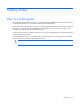
Getting started How to use this guide This guide provides procedures and solutions for troubleshooting an HP BladeSystem c-Class enclosure, from using the Insight Display to more complex component-level troubleshooting. Always begin the troubleshooting process by using the Insight Display Health Summary screen to resolve all reported errors. If the procedures provided by the Insight Display do not correct the issue, then use the procedures in this guide to further troubleshoot the issue.
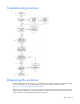
Troubleshooting overview Diagnosing the enclosure When troubleshooting an enclosure, be sure that the enclosure and all components are installed properly. For more information, see the HP BladeSystem c-Class Solution Overview on the HP website (http://www.hp.com/go/bladesystem/documentation). When the system is powered on and the Insight Display is operating properly, use the Insight Display for diagnosing and troubleshooting.
The Insight Display is powered off when the overall health is good to save the life of the Insight Display. Diagnosing the overall system health Background color Description Green System health is good. Amber System health is degraded. Blue Enclosure UID is active. Enclosure UID overrides the green and amber background colors. Use the Insight Display main menu to turn the enclosure UID on and off.
The Main Menu appears: The Main Menu of the Insight Display has the following menu options: • Health Summary • Enclosure Settings • Enclosure Info • Blade or Port Info • Turn Enclosure UID on/off • View User Note • Chat Mode • USB Menu—This option is available on Onboard Administrator version 2.30 and later. • KVM Menu—This option is available if the enclosure supports KVM.
Errors are placed in the following error categories: • Device errors include device failures, degraded devices, or information messages about a component. • Location errors include missing components or components installed in the wrong bay. • Configuration errors include problems with server blades and the corresponding interconnect modules. • Power errors include insufficient power for a device or the power subsystem redundancy is degraded.
The error category is displayed at the top of the summary screen. To view additional information for each error in the category, use the arrow keys on the Insight Display to select Details. To view the details for other errors in this category, select Next or Prev, and then press the OK button to scroll through all errors. The type and number of errors are displayed at the top of the error screen.
This symbol indicates the presence of hazardous energy circuits or electric shock hazards. Refer all servicing to qualified personnel. WARNING: To reduce the risk of injury from electric shock hazards, do not open this enclosure. Refer all maintenance, upgrades, and servicing to qualified personnel. This symbol indicates the presence of electric shock hazards. The area contains no user or field serviceable parts. Do not open for any reason.
WARNING: To reduce the risk of electric shock or damage to the equipment: • Do not disable the power cord grounding plug. The grounding plug is an important safety feature. • Plug the power cord into a grounded (earthed) electrical outlet that is easily accessible at all times. • Unplug the power cord from the power supply to disconnect power to the equipment. • Do not route the power cord where it can be walked on or pinched by items placed against it.
• Use heel straps, toe straps, or boot straps at standing workstations. Wear the straps on both feet when standing on conductive floors or dissipating floor mats. • Use conductive field service tools. • Use a portable field service kit with a folding static-dissipating work mat. If you do not have any of the suggested equipment for proper grounding, have an authorized reseller install the part.
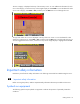
Common problem resolution Troubleshooting with the HP BladeSystem Insight Display Always begin troubleshooting the enclosure by using the Insight Display as follows: 1. 2. Check the Insight Display screen. o If the Insight Display background color is green, then the enclosure is operating normally and has no errors. No further action is required. o If the Insight Display background color is blue, then the enclosure UID is active. The enclosure UID color overrides the green or amber colors.
Service notifications To view the latest service notifications, refer to the HP website (http://www.hp.com/go/bizsupport). Select the appropriate server model, and then click the Troubleshoot a Problem link on the product page. Firmware updates Download firmware updates from the following locations: • HP BladeSystem c-Class Firmware and Upgrades compatibility matrix on the HP website (http://www.hp.
HP BladeSystem Insight Display troubleshooting Insight Display overview The Insight Display enables the rack technician to configure the enclosure initially. It also provides information about the health and operation of the enclosure. See the HP BladeSystem Onboard Administrator User Guide for additional information. The Insight Display background color varies with the condition of the enclosure health: • Blue—The Insight Display background illuminates blue when the enclosure UID is active.
• Always read any Warnings and Cautions before beginning the troubleshooting procedure. • Always begin with the step indicated by the symptom. • Perform the operation described in the step, then evaluate the result of that action and perform any additional procedures as directed. If the issue is not resolved, then continue to the next step. For specific removal and replacement procedures, see the appropriate enclosure maintenance and service guide located on the HP website (http://www.hp.
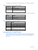
Step HP BladeSystem c3000 Enclosure Insight Display action and verification Step 3 Action Verify the number of OA modules installed in the enclosure. Verification If only one OA module is installed in the enclosure, continue to step 6. If two OA modules are installed in the enclosure, continue to the next step. Step 4 Action Identify the active OA module. Verification If the active OA LED is illuminated on the left OA module (OA1), then reseat the left OA module. Continue to the next step.
Symptoms: HP BladeSystem c7000 Enclosure Insight Display Symptoms Initial step Required steps Begin with step 1. The display screen is off, and the buttons Press any Insight Display button to try to wake up the display. The Insight Display do not operate. powers on automatically if the health is good. The display screen flashes, and the Insight Press any Insight Display button to stop the Begin with step 1. flashing. The Insight Display flashes when Display buttons do not operate.
Step HP BladeSystem c7000 Enclosure Insight Display action and verification Step 2 Action Check the Insight Display to be sure that no firmware updates are in progress. Verification Do one of the following: • • Step 3 Action If one Onboard Administrator is installed in the enclosure, then continue to step 4.
Step HP BladeSystem c7000 Enclosure Insight Display action and verification Static OA1 IP settings: 1 2 Use the Insight Display Enclosure Settings information to change the OA1 IP address to static. Enter the following information recorded in the previous step: -IP address -Netmask -Gateway 3 Record or tear off the replaced Onboard Administrator password from the label on the OA tray. DHCP OA IP settings: 1 2 Use the Insight Display Enclosure Settings information to change the OA1 IP address to DHCP.
Step HP BladeSystem c7000 Enclosure Insight Display action and verification Configuration Complete the configuration: 1 2 3 4 Step 9 Log in to OA #Y using the Administrator account and the new password. Verify that the standby Onboard Administrator (OA #X) firmware is the correct version. Update the active Onboard Administrator firmware, if necessary, to synchronize the firmware on both Onboard Administrators. This update also synchronizes the enclosure settings on the standby Onboard Administrator.
Step HP BladeSystem c7000 Enclosure Insight Display action and verification Verification Wait for up to 2 minutes, and then check the Insight Display. • • If the issue still exists, then continue to the next step. If the Insight Display illuminates and the Insight Display buttons operate, then complete the repair by replacing the original OA tray. To replace the OA tray: 1 2 3 4 5 6 7 Step 13 Install the metal cover. Install the devices in the original device bays. Remove OA #X from OA bay X.
Enclosure troubleshooting Troubleshooting guidelines Observe the following guidelines when performing troubleshooting procedures: • Always read any Warnings and Cautions before beginning the troubleshooting procedure. • Always begin with the step indicated by the symptom. • Perform the operation described in the step, then evaluate the result of that action and perform any additional procedures as directed. If the issue is not resolved, then continue to the next step.
CAUTION: If you are using a Virtual Connect environment, some of these procedures might cause the loss of Virtual Connect credentials and the loss of communication between the Onboard Administrator and the Virtual Connect Interconnect module. Ensure the Virtual Connect configuration is backed up before proceeding with any of the following procedures. Virtual Connect configuration can be backed up by using Virtual Connect GUI or Virtual Connect Support Utility. To correct a configuration error: 1.
Device errors occur when a component has degraded health, a non-critical device-specific error, or has failed. Device errors might occur on all components, including: • Server blades • Storage blades • Power supplies • Interconnect modules • Onboard Administrator modules • Fans • AC power inputs To correct a device error: 1. Use the arrow buttons to navigate to Fix This, and press OK. 2. Review and complete the corrective action suggested by the Insight Display.
Fan LED condition Initial step Required steps A fan LED is solid green, and the Insight Display reports a location error Verify the fan population. A fan is located in the wrong bay according to the fan population rule. Access more information from the Onboard Administrator and iLO 2. To correct the issue, follow the Insight Display steps. Begin by selecting Fix on the Insight Display. All fan LEDs are solid green, but fans in this enclosure are running at a higher speed than normal.
Step Fan LED is flashing amber action and verification Step 5 Action Complete each step in the "Troubleshooting the Insight Display (on page 16)" section depending on the enclosure. Perform the verification in this step after completing each Insight Display troubleshooting step. Verification If the fan health LED continues to flash after verifying each of the Insight Display troubleshooting steps, then continue to the next Insight Display troubleshooting step.
Step Fan LED is off action and verification Verification If the fan LED for the fan in the suspect bay is green, then return all fans to their original fan bays. The repair is complete. If the suspect fan LED remains off, then continue to the next step. Step 4 Action Depending on the enclosure, complete each step in the "Troubleshooting the Insight Display (on page 16)" section. Perform the verification in this step after completing each Insight Display troubleshooting step.
Step Fan LED is solid amber action and verification Verification If the error still exists, then replace the fan to complete the repair. If the fan LED is solid green, then continue to the next step. Step 3 Action Install an operational fan into the suspect fan bay. Verification If the fan LED is green, then return all fans to their original fan bays. Replace the suspect fan to complete the repair. If an operational fan LED is solid amber, then continue to the next step.
Procedures: Power supply failure CAUTION: Some troubleshooting procedures require powering down an entire enclosure. To avoid possible data loss, always secure permission before powering down an enclosure. CAUTION: If you are using a Virtual Connect environment, some of these procedures might cause the loss of Virtual Connect credentials and the loss of communication between the Onboard Administrator and the Virtual Connect Interconnect module.
Step Power supply failure action and verification Step 4 Action To troubleshoot the component connectors, perform the following: 1 2 3 4 Note the location of each device to be sure that each device is later installed in the original bay. Remove all devices and modules installed in the enclosure. Attempt to keep cables attached to all rear modules. If this is not possible, then note cable locations to be sure the cables are connected to the module correctly when the module is reinstalled.
Step Power supply failure action and verification Verification If the Onboard Administrator health LED is green and a second Onboard Administrator was originally installed, then continue to step 10. If the power supply fault LEDs are on, then continue to the next step. For all other LED indications, continue to step 13. Step 9 Action Remove the suspect Onboard Administrator from OA bay 1. Install an operational Onboard Administrator in OA bay 1.
Step Power supply failure action and verification Verification If the Onboard Administrator health LEDs are green, then the OA tray failed. Continue to the next step. If the power supply fault LEDs are on, then the original OA tray did not fail. Remove all Onboard Administrators and the current OA tray. Install the original OA tray and the Onboard Administrators in the original locations. Continue to the next.
Error indication Initial step Required steps A server blade does not power up. The following conditions exist: — To correct the issue, follow the Insight Display steps. After each step, check the device bay status on the Insight Display Health Summary screen. When the status changes from black to another color, the Onboard Administrator detects the server blade. The server blade is not seated properly in the device bay. Reseat the server blade in the device bay.
Error indication Initial step Required steps A server blade is powered up. The following conditions exist: No iLO 2 IP address results in the following conditions: • • • • The iLO 2 on this server blade has no IP address. To configure the iLO 2 IP address, reboot the server blade and use the iLO 2 ROM setup during POST. The power LED is green. The health LED is green. The Insight Display device bay status is blue. • • • A server blade is powered up.
Error indication Initial step Required steps A server blade is powered up. The following conditions exist: — Inspect the server IML log for the specific error report. The IML can be reached through the OA GUI/CLI and through iLO2 GUI. If not using the HP OS agents, then an error may not be logged and a memory error is indicated. Correct the issue listed in the IML log. If no issue is listed, then contact HP for support. • • • The power LED is green. The health LED is flashing amber.
Step Server blade errors action and verification Verification If connector damage is visible, then dispose of the damaged server blade. Never install the damaged server blade in an enclosure. Continue to the next step. If the signal and power connectors are not damaged, then continue to the next step. Step 3 Action Visually examine the suspect midplane assembly signal and power connectors in the suspect bay.
Step Server blade errors action and verification Step 8 Action If troubleshooting an HP BladeSystem c3000 Enclosure, then remove the c3000 OA tray and replace it with a service spare part. If troubleshooting an HP BladeSystem c7000 Enclosure, then continue to the next step. Verification If the server blade powers up, then the original BladeSystem c3000 OA tray failed. Continue to step 13.
Step Server blade errors action and verification Step 13 Action Obtain the OA1 IP settings from the enclosure administrator. Static OA1 IP settings: 1 2 Use the Insight Display Enclosure Settings information to change the OA1 IP address to static. Enter the following information recorded in the previous step: -IP address -Netmask -Gateway 3 Record or tear off the replaced Onboard Administrator password from the label on the OA tray.
Step Server blade errors action and verification Verification Wait for up to 2 minutes, then check the Insight Display. If the Insight Display illuminates and the Insight Display buttons operate properly, then install OA #Y, if present, in OA bay Y to complete the repair. If the issue still exists, continue to the next step. Step 18 Action Replace the OA tray: 1 2 3 4 Remove OA #X. Remove the OA tray. Install a service spare OA tray. Install OA #X in bay X.
Procedures: Partner blade errors CAUTION: Some troubleshooting procedures require powering down an entire enclosure. To avoid possible data loss, always secure permission before powering down an enclosure. CAUTION: If you are using a Virtual Connect environment, some of these procedures might cause the loss of Virtual Connect credentials and the loss of communication between the Onboard Administrator and the Virtual Connect Interconnect module.
Step Partner blade errors action and verification Verification If the partner blade health LED is green, then the connection is restored. The repair is complete. If the partner blade health LED is off, then continue to the next step. Step 5 Action To troubleshoot the suspect Onboard Administrator, remove the suspect Onboard Administrator and install an operational Onboard Administrator or service spare part.
Symptom Initial step Required steps The Onboard Administrator health LED is — off on one Onboard Administrator, and Onboard Administrator health LED is green on the second Onboard Administrator. The Onboard Administrator health LED is — Begin with step 2. — Begin with step 2. Begin with step 1. off on both Onboard Administrators. The Onboard Administrator LED is red. Procedures: Onboard Administrator errors CAUTION: Some troubleshooting procedures require powering down an entire enclosure.
Step Onboard Administrator errors action and verification Verification If the Onboard Administrator health LED is green, then the connection is restored. The repair is complete. If the Onboard Administrator health LED is off, then continue as follows: • • Step 3 If troubleshooting an HP BladeSystem c7000 Enclosure, then continue to the next step. If troubleshooting an HP BladeSystem c3000 Enclosure, then continue to step 6.
Step Onboard Administrator errors action and verification Verification Wait until the Insight Display indicates that the second or non-suspect Onboard Administrator has completed power-on tests. If the second or non-suspect HP BladeSystem c3000 OA operates properly, then replace the suspect Onboard Administrator and continue with step 9. If the second or non-suspect OA has the same issue as the suspect OA, and the suspect OA is OA1, then continue to the next step.
Step Onboard Administrator errors action and verification Configuration When the IP address is updated for the new Onboard Administrator, then the hardware repair is complete. To complete the configuration, perform the following steps: 1 2 3 4 5 If the OA1 IP address is 0.0.0.0 and is set for DHCP, then have the network administrator modify the DHCP server configuration to add the new OA MAC address. The OA MAC address is found in the new OA default DNS name.
CAUTION: If you are using a Virtual Connect environment, some of these procedures might cause the loss of Virtual Connect credentials and the loss of communication between the Onboard Administrator and the Virtual Connect Interconnect module. Ensure the Virtual Connect configuration is backed up before proceeding with any of the following procedures. Virtual Connect configuration can be backed up by using Virtual Connect GUI or Virtual Connect Support Utility.
Step Interconnect module errors action and verification Verification If the interconnect module health LED is green, then the Onboard Administrator failed. The repair is complete. If the interconnect module health LED is off, then the suspect Onboard Administrator is not causing the error. • • Step 6 If troubleshooting an HP BladeSystem c7000 Enclosure, then continue to the next step. If troubleshooting an HP BladeSystem c3000 Enclosure, then continue to step 7.
Procedures: Enclosure DVD-ROM troubleshooting CAUTION: Some troubleshooting procedures require powering down an entire enclosure. To avoid possible data loss, always secure permission before powering down an enclosure. CAUTION: To avoid data loss, do not remove an Onboard Administrator when the Insight Display shows a firmware update in progress. During this activity, the Insight Display displays the Firmware Update screen with the Lock icon and the firmware update progress bar.
Step Enclosure DVD-ROM troubleshooting action and verification Verification The Insight Display displays a locked symbol for a short time. 1 2 When the locked symbol no longer appears, navigate to the DVD Connect Status screen. Verify that the DVD-ROM status icon next to the selected button is green, indicating that the server blade is connected to the DVD-ROM drive. The selected button should now read "Disconnect.
Step DVD-ROM drive troubleshooting action and verification Step 4 Action Press the eject button on the DVD-ROM drive. Verification If the DVD-ROM drive ejects, then the repair is complete. If the DVD-ROM drive does not eject, then proceed to step 2 of "Procedures: HP BladeSystem c3000 Enclosure DVD-ROM troubleshooting (on page 52)." Step 5 Action Connect to the DVD-ROM drive: 1 2 3 Use the Insight Display to navigate to the Enclosure Settings screen. Select DVD Drive 'Connect…' Press the OK button.
CAUTION: To avoid data loss, do not remove an Onboard Administrator when the Insight Display shows a firmware update in progress. During this activity, the Insight Display displays the Firmware Update screen with the Lock icon and the firmware update progress bar. Step HP BladeSystem c3000 Enclosure DVD-ROM troubleshooting action and verification Step 1 Action Check the DVD-ROM drive status on the Insight Display Health Summary screen.
Step HP BladeSystem c3000 Enclosure DVD-ROM troubleshooting action and verification Step 4 Action 1 2 Use the Insight Display up arrow key to select 'Enable…'. Press the OK button twice to accept the changes. This changes the USB setting to toggle the USB enable from rear to front or front to rear as indicated in the selected action. The Onboard Administrator reboots after changing this setting.
Step External DVD-ROM troubleshooting action and verification Verification If no indication of power to the DVD-ROM drive exists and the Insight Display does not detect a DVD-ROM drive, then continue to the next step. If the DVD-ROM drive tray opened, and the Insight Display Health Summary DVD-ROM status is gray, continue to step 1 of "Procedures: Enclosure DVD-ROM troubleshooting (on page 50).
Step External DVD-ROM troubleshooting action and verification Step 7 Action Test the OA module connection: 1 2 3 4 Reseat the OA module. Wait for OA to reboot. Navigate to the Insight Display Health Summary screen. Verify the DVD-ROM drive status. Verification If the DVD-ROM drive status is gray or green, then the repair is complete. If the DVD-ROM drive status is black, continue to step 1 of "Onboard Administrator troubleshooting (on page 43).
Symptom Initial step Required steps When typing in Linux GUI windows (X11), multiple characters appear. — Begin with step 2 of "Procedures: KVM Linux troubleshooting (on page 60)." The mouse cursor does not appear on the Linux GUI. — Begin with step 1 of "Procedures: KVM mouse problems (on page 61)." Procedures: External KVM switch troubleshooting CAUTION: Some troubleshooting procedures require powering down an entire enclosure.
Step External KVM switch troubleshooting action and verification Step 5 Action 1 2 3 Press the KVM keyboard Print Screen key. Use the external KVM Switch Port Selection menu to select the port connected to the c3000 KVM module. Press the KVM keyboard Print Screen key a second time to dismiss the External KVM Switch menu and to activate the c3000 enclosure KVM Menu. Verification If the Enclosure KVM Menu appears, then the repair is complete.
The KVM monitor must support a minimum resolution of 1024x768 to operate properly with the c3000 KVM module. Step External KVM monitor troubleshooting action and verification Step 1 Action Connect the KVM monitor directly to a server blade VGA connector. Step 2 Action Connect the KVM keyboard directly to the server blade USB connector. Step 3 Action If the server blade is in screen-saver mode, press the Shift key.
Procedures: KVM module troubleshooting CAUTION: Some troubleshooting procedures require powering down an entire enclosure. To avoid possible data loss, always secure permission before powering down an enclosure. CAUTION: To avoid data loss, do not remove an Onboard Administrator when the Insight Display shows a firmware update in progress. During this activity, the Insight Display displays the Firmware Update screen with the Lock icon and the firmware update progress bar.
CAUTION: To avoid data loss, do not remove an Onboard Administrator when the Insight Display shows a firmware update in progress. During this activity, the Insight Display displays the Firmware Update screen with the Lock icon and the firmware update progress bar. The Onboard Administrator firmware must be version 2.10 or later to support the c3000 KVM module.
Symptoms: Insight Display reports blue device errors Symptom Additional information The Insight Display Health Summary screen reports a device bay with a "blue" color. After rebooting the Onboard Administrator, it can take up to 5 minutes for all start-up processes to complete. During this time, various devices and fans may display a blue status. A long-lasting "blue" device color Begin with step 1.
Step Insight Display reports blue device errors action and verification Step 1 Action Reseat the Onboard Administrators and the OA tray: 1 2 3 4 Remove all Onboard Administrators installed in the enclosure. Remove the OA tray. Install the OA tray in the original bay. Install the Onboard Administrators in the original bays. The active Onboard Administrator automatically reboots. Verification If the Insight Display no longer reports any blue devices, then the repair is complete.
Step Insight Display reports blue device errors action and verification Verification Wait for the Onboard Administrator power-on to complete. When powered-on, if the device appears green on the Insight Display Health Summary screen, then the repair is complete. If the device appears blue after completion of the power-on delay sequencing, continue to the next step. Step 6 Action Remove the device in the blue bay, and then install it into an operational bay.
command. This causes an interruption in the I/O connectivity, so update per module and not all together. 6. To review any connectivity issues with 1 or 10GB PatchPanel, install the latest Patch Panel Interconnect Firmware. 7. Capture any entry in the OA syslog file referring to Saving supportdump by using the OA CLI command upload supportdump, and then send it to HP Support for analysis where needed.
Midplane assembly replacement Midplane assembly troubleshooting Historic service data collected on the c-Class Enclosures suggests that midplane hardware failures are very rare. Therefore, midplane replacements must only be made as a last resort. Midplane connections are 100% copper to copper connections for the data-ports. These connections hardly brake during a normal day to day operation.
o Failover the VC domain to the other VC module by using the reset vcm –failover command and retesting the blade. o Back up the VC domain configuration by using VCSU or VC GUI. o Delete the VC domain and restore the VC domain and retry (the domain could be corrupted causing a server not to assign a profile correctly). 9. If an entire row (bottom or top) of fans is not working, then replace the midplane. 10. If further help is needed, contact HP Support and provide the OA SHOW ALL output.
4. Disengage and extend the following components approximately 8 cm (3 in): o Half-height and full-height blades o Power supplies — The power supply in bay 3 or 4 must be completely removed, and then the Insight Display must be moved in front of that power supply bay to enable the other power supplies to be removed or extended. 5. Remove the enclosure fans. 6. Remove the interconnect switches and Pass-Thru modules. 7. Remove the Onboard Administrator modules. 8.
1. When installing the midplane assembly onto the rear cage assembly, ensure the LCD cable is routed behind the interconnect module rubber boot and through the sheet-metal gaps. Route the cable as shown in the following figure. 2. Route the cable between the Insight Display signal pass-thru board pin guide and the screw mounts. Be careful not to pinch the cable between the Insight Display signal pass-thru board and the screw mount as shown in the following figure. 3.
2. 3. Verify that the enclosure serial number matches the enclosure serial number on the label on the enclosure mounting bracket. o If the enclosure serial number matches the label, continue to step 7. o If the enclosure serial number does not appear or does not match the label, continue to step 3 to manually update the enclosure identity using the Onboard Administrator CLI.
Step Midplane assembly replacement action and verification Caution Request authorization to power down the enclosure. Do not continue to the next step until you receive proper authorization. Guidelines • • Step 1 Action Contact an authorized service provider to perform the following steps: 1 2 3 4 5 6 7 8 9 10 11 Step 2 To be sure that each device is reinstalled in the original location, note the location of each device.
Step Midplane assembly replacement action and verification Step 4 Action Perform PDU part number update using the following OA CLI command: set enclosure PDU_type X Where X represents 1, 2, 3, or 4 according to the power setup: • • • • Step 5 1 2 3 4 for for for for single-phase power three-phase power, North America three-phase power, international DC power Action Install all server blades and interconnect modules in the original locations.
Component identification HP BladeSystem c7000 Enclosure components Enclosure front components Item Description 1 Device bays* 2 Air intake slot (Do not block.) 3 Power supply bay 1 4 Power supply bay 2 5 Power supply bay 3 6 Power supply bay 4 7 Insight Display 8 Power supply bay 5 9 Power supply bay 6 10 Air intake slot (Do not block.) *For more information, see "Device bay numbering.
Device bay numbering Each enclosure requires interconnects to provide network access for data transfer. Interconnects reside in bays located on the rear of the enclosure. Be sure to review device bay numbering to determine which external network connections on the interconnects are active. IMPORTANT: When looking at the rear of the enclosure, front device bay numbering is reversed.
Power supply LEDs Power LED 1 (green) Fault LED 2 (amber) Condition Off Off No AC power to the power supply On Off Normal Off On Power supply failure Power supply bay numbering Component identification 75
HP BladeSystem Insight Display Insight Display overview The Insight Display enables the rack technician to configure the enclosure initially. It also provides information about the health and operation of the enclosure. See the HP BladeSystem Onboard Administrator User Guide for additional information. The Insight Display background color varies with the condition of the enclosure health: • Blue—The Insight Display background illuminates blue when the enclosure UID is active.
Accessing the Insight Display on the HP BladeSystem c7000 Enclosure The Insight Display is located on the front of the HP BladeSystem c7000 Enclosure. The Insight Display slides from side to side to allow access to enclosure components.
Enclosure rear components Item Description 1 Fan bay 1 2 Fan bay 2 3 Fan bay 3 4 Fan bay 4 5 Fan bay 5 6 Interconnect bay 2 7 Interconnect bay 4 8 Interconnect bay 6 9 Interconnect bay 8 10 Onboard Administrator bay 2 11 OA tray 12 Power supply exhaust vent (do not block) 13 Fan bay 10 14 Fan bay 9 15 Fan bay 8 16 Fan bay 7 17 Fan bay 6 18 AC power connectors 19 Onboard Administrator bay 1 20 Interconnect bay 7 21 Interconnect bay 5 22 Interconnect bay 3 23 In
Interconnect bay numbering To support network connections for specific signals, install the interconnect module into the appropriate bay. Server blade signal Interconnect bay number NICs 1, 2, 3, and 4 (embedded) 1, 2 Mezzanine 1 3, 4 Mezzanine 2 5, 6 and then 7, 8 Mezzanine 3 7, 8 and then 5, 6 Interconnect bay label For information on the location of LEDs and ports on individual interconnect modules, see the documentation that ships with the interconnect module.
Onboard Administrator components Item Description 1 Onboard Administrator bay 1 2 Onboard Administrator bay 2 (redundant, if used) 3 Enclosure link-up port 4 Enclosure link-down port Onboard Administrator LEDs and buttons Item Description 1 Onboard Administrator UID LED 2 Enclosure UID LED and UID button 3 Onboard Administrator active LED Component identification 80
Item Description 4 Onboard Administrator health LED 5 Onboard Administrator reset button Fan bay numbering Fan LED LED color Fan status Solid green The fan is working. Solid amber The fan has failed. Flashing amber See the Insight Display screen.
HP BladeSystem c3000 Enclosure components Enclosure front components Item Description 1 Device bays 2 CD/DVD-ROM drive blank or CD/DVD-ROM drive (optional) 3 Onboard Administrator tray (reserved for future use) 4 Insight Display 5 Onboard Administrator tray containing Onboard Administrator 1. Device bay numbering Each enclosure requires interconnects to provide network access for data transfer. Interconnects reside in bays located on the rear of the enclosure.
Full-height device bay numbering Half-height device bay numbering Component identification 83
HP BladeSystem Insight Display components Item Description Function 1 Insight Display screen Displays Main Menu error messages and instructions 2 Left arrow button Moves the menu or navigation bar selection left one position 3 Right arrow button Moves the menu or navigation bar selection right one position 4 OK button Accepts the highlighted selection and navigates to the selected menu 5 Down arrow button Moves the menu selection down one position 6 Up arrow button Moves the menu select
Item Description 2 Onboard Administrator bay 2 (redundant, if used) 3 Enclosure link-up port 4 Enclosure link-down port Accessing the Insight Display on the HP BladeSystem c3000 Enclosure 1. To access the Insight Display, push on the exposed end. 2. Pull the Insight Display out of the chassis to lock it into place, and then tilt it up.
3. Rotate the Insight Display 90 degrees to view the display.
Item Description 9 Power supply bays ("Power supply bay numbering" on page 88) 10 Interconnect bay 4 11 Interconnect bay 3 Fan bay numbering Fan LEDs LED color Fan status Solid green The fan is working. Solid amber The fan has failed. Flashing amber See the Insight Display screen.
Power supply bay numbering Power supply LED Power LED Status Off No AC power to power supply units Green AC is present. Standby output is on, output is disabled. Green AC is present. Standby output is on, power supply DC output is on and OK.
Interconnect bay numbering To support network connections for specific signals, install the interconnect module in the appropriate bay.
Software tools and solutions Server blade diagnostic tools HP Insight Diagnostics HP Insight Diagnostics is a proactive server blade management tool, available in both offline and online versions, that provides diagnostics and troubleshooting capabilities to assist IT administrators who verify server blade installations, troubleshoot problems, and perform repair validation. HP Insight Diagnostics Offline Edition performs various in-depth system and component testing while the OS is not running.
• From within the iLO 2 user interface • From within HP Insight Diagnostics (on page 90) • From within the Onboard Administrator GUI For more information, see the HP BladeSystem Onboard Administrator User Guide on the HP website (http://www.hp.com/go/bladesystem/documentation). • From the Onboard Administrator CLI See the HP BladeSystem Onboard Administrator Command Line Interface User Guide for information on accessing the CLI.
Management tools HP Systems Insight Manager HP SIM is a web-based application that allows system administrators to accomplish normal administrative tasks from any remote location, using a web browser. HP SIM provides device management capabilities that consolidate and integrate management data from HP and third-party devices. IMPORTANT: You must install and use HP SIM to benefit from the Pre-Failure Warranty for processors, SAS and SATA hard drives, and memory modules.
4. Use the firmware update tool to perform the firmware update. For more information on how to use the tool, see the documentation provided with the tool. Verifying firmware versions Operating systems • Verify the HP BladeSystem firmware by using the Onboard Administrator.
System maintenance tools Drivers IMPORTANT: Always perform a backup before installing or updating device drivers. The server blade includes new hardware that may not have driver support on all OS installation media. If you are installing a SmartStart-supported OS, use the SmartStart software and its Assisted Path feature to install the OS and latest driver support. If you are installing drivers from the SmartStart CD, be sure that you are using the latest SmartStart version that your server blade supports.
Operating system version support Refer to the operating system support matrix (http://www.hp.com/go/supportos). HP Smart Update Manager The HP Smart Update Manager enables system administrators to upgrade ROM images efficiently across a wide range of servers and options.
2. Shut down each target server blade, and then reboot using the correct ROMPaq diskette or USB drive key for that server blade. 3. Follow the interactive session in the ROMPaq utility, and then select the devices to be flashed. 4. After the ROMPaq utility flashes the ROM for the selected devices, cycle power manually to reboot the system back into the operating system. Option ROMPaqs have been retired as an upgrade delivery method for storage options.
Contacting HP Contacting HP technical support or an authorized reseller Before contacting HP, always attempt to resolve problems by completing the procedures in this guide. IMPORTANT: Collect the appropriate server information ("Server information you need" on page 97) and operating system information ("Operating system information you need" on page 98) before contacting HP for support. For the name of the nearest HP authorized reseller: • See the Contact HP worldwide (in English) webpage (http://welcome.
• Explanation of the issue, the first occurrence, and frequency • Any changes in hardware or software configuration before the issue surfaced • Third-party hardware information: • • o Product name, model, and version o Company name Specific hardware configuration: o Product name, model, and serial number o Number of processors and speed o Number of DIMMs and their size and speed o List of controllers and NICs o List of connected peripheral devices o List of any other optional HP or Co
o Event logs o Dr. Watson log (drwtsn32.
• o /etc/modules.conf or etc/conf.modules o /etc/lilo.conf or /etc/grub.conf o /etc/fstab If HP drivers are installed: o Version of the PSP used o List of drivers from the PSP (/var/log/hppldu.
Sun Solaris operating systems Collect the following information: • Operating system version number • Type of installation selected: Interactive, WebStart, or Customer JumpStart • Which software group selected for installation: End User Support, Entire Distribution, Developer System Support, or Core System Support • If HP drivers are installed with a DU: • o DU number o List of drivers in the DU diskette The drive subsystem and file system information: o Number and size of partitions and logic
Acronyms and abbreviations ADU Array Diagnostics Utility CLI Command Line Interface DHCP Dynamic Host Configuration Protocol DNS domain name system DU driver update EBIPA Enclosure Bay IP Addressing FRU field replaceable unit HP SIM HP Systems Insight Manager I/O input/output iLO Integrated Lights-Out iLO 2 Integrated Lights-Out 2 IML Integrated Management Log Acronyms and abbreviations 102
IP Internet Protocol IRQ interrupt request LDAP Lightweight Directory Access Protocol MAC Media Access Control NIC network interface card NVRAM non-volatile memory OA Onboard Administrator PDU power distribution unit PID product ID POST Power-On Self Test PSP ProLiant Support Pack SNMP Simple Network Management Protocol SSH Secure Shell UID unit identification Acronyms and abbreviations 103
USB universal serial bus VCSU Virtual Connect Support Utility Acronyms and abbreviations 104
Index A ADU (Array Diagnostic Utility) alerts 16, 24, 25 Array Diagnostic Utility (ADU) authorized reseller 97 authorized technician 11 91 91 B bay numbering, fan 78, 87 bay numbering, full-height device 74, 83 bay numbering, half-height device 74, 83 bay numbering, interconnect 78, 79, 89 bay numbering, power supply 75, 88 Blade and Port Info screen 7 buttons 73 buttons, Onboard Administrator 80 C cables 14 cables, troubleshooting 14 Care Pack 96 caution alerts 7 cautions 7, 11 cautions, electrical 11 c
external KVM monitor troubleshooting 58 I F fan bay numbering 78, 81, 87 fan errors 25 fan failure troubleshooting 26 fan LED 81, 87 fan status 87 fan troubleshooting procedure 27, 28, 29 fan troubleshooting, symptoms 26 fans 26, 87 features 73 firmware compatibility matrix, HP BladeSystem firmware compatibility matrix, virtual connect firmware maintenance 92, 93 firmware, updating 15, 92 firmware, upgrading 15 firmware, version 92, 93 flash ROM 92 flowcharts 6 front components 73, 82 full-height device
M management tools 92 Microsoft operating systems 98 midplane assembly 66, 67 midplane assembly replacement 66, 67, 70 midplane assembly troubleshooting 66 mouse problems 61 66, 70 S N Novell NetWare 100 numbering, device bay 74, 83 numbering, fan bays 78, 81, 87 numbering, full-height device bays 74, 83 numbering, half-height device bays 74, 83 numbering, interconnect bays 78, 89 numbering, power supply bays 75, 88 O Onboard Administrator components 80 Onboard Administrator LEDs and buttons 80 Onboard
troubleshooting, symptoms troubleshooting, troubleshooting, troubleshooting, troubleshooting, troubleshooting, troubleshooting, Onboard Administrator 43 partner blade symptoms 41 partner blades 41, 42 power supply 30, 31 remote 64 server blade 34, 37 server blade symptoms 34 U UID LED 16, 80 updating the firmware 92 upgrades compatibility matrix USB drive key 95 using this guide 5 utilities 90 92 V VCA (Version Control Agent) 94 VCRM (Version Control Repository Manager) Version Control Agent (VCA) 94 Ve