HP ProLiant BL620c G7 Server Blade Maintenance and Service Guide Abstract This guide is for an experienced service technician. HP assumes you are qualified in the servicing of computer equipment and trained in recognizing hazards in products with hazardous energy levels and are familiar with weight and stability precautions for rack installations.
© Copyright 2010, 2011 Hewlett-Packard Development Company, L.P. The information contained herein is subject to change without notice. The only warranties for HP products and services are set forth in the express warranty statements accompanying such products and services. Nothing herein should be construed as constituting an additional warranty. HP shall not be liable for technical or editorial errors or omissions contained herein. Microsoft and Windows are U.S.
Contents Customer self repair ...................................................................................................................... 5 Parts only warranty service ............................................................................................................................ 5 Illustrated parts catalog ............................................................................................................... 16 Server blade components ........................................
External USB functionality ................................................................................................................. 59 Internal SD support ..................................................................................................................................... 59 Server component identification .................................................................................................... 60 Front panel components and LEDs ..........................................
Customer self repair HP products are designed with many Customer Self Repair (CSR) parts to minimize repair time and allow for greater flexibility in performing defective parts replacement. If during the diagnosis period HP (or HP service providers or service partners) identifies that the repair can be accomplished by the use of a CSR part, HP will ship that part directly to you for replacement. There are two categories of CSR parts: • Mandatory—Parts for which customer self repair is mandatory.
Obligatoire - Pièces pour lesquelles la réparation par le client est obligatoire. Si vous demandez à HP de remplacer ces pièces, les coûts de déplacement et main d'œuvre du service vous seront facturés. Facultatif - Pièces pour lesquelles la réparation par le client est facultative. Ces pièces sont également conçues pour permettre au client d'effectuer lui-même la réparation.
In base alla disponibilità e alla località geografica, le parti CSR vengono spedite con consegna entro il giorno lavorativo seguente. La consegna nel giorno stesso o entro quattro ore è offerta con un supplemento di costo solo in alcune zone. In caso di necessità si può richiedere l'assistenza telefonica di un addetto del centro di supporto tecnico HP. Nel materiale fornito con una parte di ricambio CSR, HP specifica se il cliente deve restituire dei componenti.
defekte Teil nicht zurückschicken, kann HP Ihnen das Ersatzteil in Rechnung stellen. Im Falle von Customer Self Repair kommt HP für alle Kosten für die Lieferung und Rücksendung auf und bestimmt den Kurier-/Frachtdienst. Weitere Informationen über das HP Customer Self Repair Programm erhalten Sie von Ihrem Servicepartner vor Ort. Informationen über das CSR-Programm in Nordamerika finden Sie auf der HP Website unter (http://www.hp.com/go/selfrepair).
enviara el componente defectuoso requerido, HP podrá cobrarle por el de sustitución. En el caso de todas sustituciones que lleve a cabo el cliente, HP se hará cargo de todos los gastos de envío y devolución de componentes y escogerá la empresa de transporte que se utilice para dicho servicio. Para obtener más información acerca del programa de Reparaciones del propio cliente de HP, póngase en contacto con su proveedor de servicios local.
Neem contact op met een Service Partner voor meer informatie over het Customer Self Repair programma van HP. Informatie over Service Partners vindt u op de HP website (http://www.hp.com/go/selfrepair). Garantieservice "Parts Only" Het is mogelijk dat de HP garantie alleen de garantieservice "Parts Only" omvat. Volgens de bepalingen van de Parts Only garantieservice zal HP kosteloos vervangende onderdelen ter beschikking stellen.
No caso desse serviço, a substituição de peças CSR é obrigatória. Se desejar que a HP substitua essas peças, serão cobradas as despesas de transporte e mão-de-obra do serviço.
Customer self repair 12
Customer self repair 13
Customer self repair 14
Customer self repair 15
Illustrated parts catalog Server blade components Item Description Spare part number Customer self repair (on page 5) Mechanical components 1 Access panel 610101-001 Mandatory1 2 610097-001 Mandatory1 3 Front panel/hard drive cage assembly (with backplane) Hard drive blank 392613-001 Mandatory1 4 Hardware and plastics kit 610100-001 Mandatory1 a) Heatsink blank* — — b) Left DIMM baffle — — c) Right DIMM baffle — — d) Enclosure connector cover* — — — — System components 5 P
Item Description Spare part number Customer self repair (on page 5) a) 2.27-GHz Intel® Xeon® X7560 processor ** 594893-001 Optional2 b) 2.0-GHz Intel® Xeon® X6550 processor* ** 594896-001 Optional2 c) 1.86-GHz Intel® Xeon® L7555 processor* ** 594900-001 Optional2 d) 1.86-GHz Intel® Xeon® E7530 processor* ** 594898-001 Optional2 e) 2.0-GHz Intel® Xeon® E6540 processor* ** 594899-001 Optional2 f) 1.73-GHz Intel® Xeon® E6510 processor* ** 594901-001 Optional2 g) 2.
Item 9 Description Spare part number f) PC3L-10600R 16-GB DDR3-1333, 512-MB x4 * 632204-001 Mandatory1 g) PCL3-8500R 32-GB DDR-3-1066, 512-MB x4 * 632205-001 Mandatory1 System board — — a) System board (supports Intel® Xeon® 610096-001 6500/7500 series processors only) b) System board (supports Intel® Xeon® processor 644496-001 E7-2800/E7-8800 families only) c) SAS backplane with bezel* 610097-001 10 11 Customer self repair (on page 5) Optional2 Optional2 Optional2 I/O accelerator boards* —
Item Description Spare part number Customer self repair (on page 5) 583999-001 Mandatory1 593411-001 Mandatory1 436010-001 Mandatory1 17 a) HP 4X QDR IB Mezzanine HCA for HP BladeSystem c-Class b) HP 4X DDR IB, CX-2, Dual Port Mezzanine HCA for HP BladeSystem c-Class c) HP 4X PCIe Mezzanine HCA for HP BladeSystem c-Class Storage controller — — a) Cache module, 512-MB 462975-001 Mandatory1 b) BBWC battery pack 462976-001 Mandatory1 c) Battery cable, 71 cm (28 in)* 488137-001 Mandatory1
No: Non—Certaines pièces HP ne sont pas conçues pour permettre au client d'effectuer lui-même la réparation. Pour que la garantie puisse s'appliquer, HP exige que le remplacement de la pièce soit effectué par un Mainteneur Agréé. Ces pièces sont identifiées par la mention “Non” dans le Catalogue illustré. 3 Mandatory: Obbligatorie—Parti che devono essere necessariamente riparate dal cliente.
Illustrated parts catalog 21
Removal and replacement procedures Required tools You need the following items for some procedures: • T-15 Torx screwdriver (provided inside the access panel) • HP Insight Diagnostics software ("HP Insight Diagnostics" on page 57) Safety considerations Before performing service procedures, review all the safety information. Preventing electrostatic discharge To prevent damaging the system, be aware of the precautions you need to follow when setting up the system or handling parts.
Symbols on equipment The following symbols may be placed on equipment to indicate the presence of potentially hazardous conditions. This symbol indicates the presence of hazardous energy circuits or electric shock hazards. Refer all servicing to qualified personnel. WARNING: To reduce the risk of injury from electric shock hazards, do not open this enclosure. Refer all maintenance, upgrades, and servicing to qualified personnel. This symbol indicates the presence of electric shock hazards.
• Press and release the Power On/Standby button. This method initiates a controlled shutdown of applications and the OS before the server blade enters standby mode. • Press and hold the Power On/Standby button for more than 4 seconds to force the server blade to enter standby mode. This method forces the server blade to enter standby mode without properly exiting applications and the OS. It provides an emergency shutdown method if an application stops responding.
3. Remove the server blade. 4. Place the server blade on a flat, level work surface. WARNING: To reduce the risk of personal injury from hot surfaces, allow the drives and the internal system components to cool before touching them. CAUTION: To prevent damage to electrical components, properly ground the server blade before beginning any installation procedure. Improper grounding can cause ESD. Access panel To remove the component: 1. Power down the server blade (on page 23). 2.
Hard drive blank Remove the hard drive blank. To replace the component, reverse the removal procedure. Hard drive IMPORTANT: Hot-plug capability and drive LED support are only available when a supported optional controller is installed in the server. To remove the component: 1. Back up all data on the hard drive. 2. Power down the server blade (on page 23).
3. Remove the hard drive. To replace the component, reverse the removal procedure. When adding hard drives to the server blade, observe the following general guidelines: • The system automatically sets all drive numbers. • If only one hard drive is used, install it in the bay with the lowest drive number. • Drives must be the same capacity to provide the greatest storage space efficiency when drives are grouped together into the same drive array.
4. Remove the mezzanine connector cover. To replace the component, reverse the removal procedure. Left DIMM baffle To remove the component: 1. Power down the server blade (on page 23). 2. Remove the server blade (on page 24). 3. Remove the access panel ("Access panel" on page 25). 4. If installed, remove the battery pack ("Removing the battery or capacitor pack" on page 34). 5. Disconnect the SAS/SATA cable from the SAS backplane. 6. Unroute the SAS/SATA cable.
7. Remove the left DIMM baffle. To replace the component, reverse the removal procedure. Right DIMM baffle To remove the component: 1. Power down the server blade (on page 23). 2. Remove the server blade (on page 24). 3. Remove the access panel ("Access panel" on page 25). 4. Remove the right DIMM baffle. To replace the component, reverse the removal procedure.
DIMM To remove the component: 1. Power down the server blade (on page 23). 2. Remove the server blade (on page 24). 3. Remove the access panel ("Access panel" on page 25). 4. Do one of the following: o If replacing processor 1 DIMMs, remove the right DIMM baffle ("Right DIMM baffle" on page 29). o If replacing processor 2 DIMMs, remove the left DIMM baffle ("Left DIMM baffle" on page 28). 5. Open the DIMM slot latches. 6. Remove the DIMM.
5. Remove the heatsink blank. To replace the component, reverse the removal procedure. Mezzanine card Optional mezzanine cards enable network connectivity or provide Fibre Channel support. For mezzanine card locations, see the system board components (on page 62). Because mezzanine cards are supported on multiple server blade models, the mezzanine card may have captive screws that are not required to secure it to the server blade.
4. Remove the mezzanine card. To replace the component: CAUTION: To prevent damage to the server blade, apply pressure over the mezzanine connector when installing the mezzanine card. Do not apply pressure to the edges of the card. 1. Install the mezzanine card. Press down on the connector to seat the board. 2. Install the access panel ("Access panel" on page 25). Front panel/hard drive cage assembly To remove the component: 1. Power down the server blade (on page 23). 2.
3. Remove the access panel ("Access panel" on page 25). 4. Disconnect the SAS signal and power cables. 5. Loosen the thumbscrews. 6. Remove the two screws from the sides of the server blade. 7. Remove the front panel/hard drive cage assembly. To replace the component, reverse the removal procedure. Battery-backed write cache procedures Two types of procedures are provided for the cache module option: • • Removal and replacement of failed components.
3. Remove the access panel ("Access panel" on page 25). 4. If installed, remove the mezzanine card on mezzanine connector 3. 5. Locate the cache module ("System board components" on page 62). 6. Disconnect the battery cable. 7. Remove the cache module. To replace the component, reverse the removal procedure.
To remove the component: 1. Power down the server blade (on page 23). 2. Remove the server blade (on page 24). 3. Remove the access panel ("Access panel" on page 25). 4. Disconnect the cable. 5.
IMPORTANT: The battery pack might have a low charge when installed. In this case, a POST error message is displayed when the server blade is powered up, indicating that the battery pack is temporarily disabled. No action is necessary on your part. The internal circuitry automatically recharges the batteries and enables the battery pack. This process might take up to four hours. During this time, the cache module functions properly, but without the performance advantage of the battery pack.
2. Remove the server blade (on page 24). 3. Remove the access panel ("Access panel" on page 25). 4. Remove all hard drives ("Hard drive" on page 26). 5. Remove all hard drive blanks ("Hard drive blank" on page 26). 6. Remove the front panel/hard drive cage assembly ("Front panel/hard drive cage assembly" on page 32). 7. Remove the heatsink. To replace the component: 1. Clean the old thermal grease from the processor with the alcohol swab. Allow the alcohol to evaporate before continuing. 2.
CAUTION: When tightening the heatsink screws, first tighten the front screw four to five turns, tighten the back screw completely, and then finish tightening the front screw. 3. Install the heatsink. 4. Install the front panel/hard drive cage assembly ("Front panel/hard drive cage assembly" on page 32). 5. Install the hard drives ("Hard drive" on page 26). 6. Install the hard drive blanks ("Hard drive blank" on page 26). 7. Install the access panel ("Access panel" on page 25). 8.
5. Remove all hard drive blanks ("Hard drive blank" on page 26). 6. Remove the front panel/hard drive cage assembly ("Front panel/hard drive cage assembly" on page 32). 7. Remove the heatsink ("Heatsink" on page 36). 8. Open the processor locking lever and the processor socket retaining bracket. 9. Using the processor tool, remove the processor from the system board: a. Line up the processor tool, ensuring the locking lever graphic on the tool is oriented correctly. b.
10. Carefully rotate the tool, and then push in and release the tabs to secure the processor in the tool. CAUTION: To avoid damage to the processor, do not touch the bottom of the processor, especially the contact area. To replace the component: 1. Carefully insert the processor into the processor installation tool. Handle the processor by the edges only, and do not touch the bottom of the processor, especially the contact area.
2. Be sure the tool is oriented correctly. Align the processor installation tool with the socket, and then install the processor. THE PINS ON THE SYSTEM BOARD ARE VERY FRAGILE AND EASILY DAMAGED. CAUTION: THE PINS ON THE SYSTEM BOARD ARE VERY FRAGILE AND EASILY DAMAGED. To avoid damage to the system board: • Never install or remove a processor without using the processor installation tool. • Do not touch the processor socket contacts.
3. Press and hold the tabs on the processor installation tool to separate it from the processor, and then remove the tool. 4. Close the processor socket retaining bracket and the processor locking lever. CAUTION: Be sure to close the processor socket retaining bracket before closing the processor locking lever. The lever should close without resistance. Forcing the lever closed can damage the processor and socket, requiring system board replacement. 5.
6. Apply all the grease to the top of the processor in the following pattern to ensure even distribution. CAUTION: Orient the heatsink as indicated in the procedure. Otherwise, you cannot install the hard drive cage. CAUTION: When tightening the heatsink screws, first tighten the front screw four to five turns, tighten the back screw completely, and then finish tightening the front screw. 7. Install the heatsink. 8.
System board To remove the component: 1. Power down the server blade (on page 23). 2. Remove the server blade (on page 24). 3. Remove the access panel ("Access panel" on page 25). 4. Remove all hard drives ("Hard drive" on page 26). 5. Remove all hard drive blanks ("Hard drive blank" on page 26). 6. Remove the front panel/hard drive cage assembly ("Front panel/hard drive cage assembly" on page 32). 7. Remove the left DIMM baffle ("Left DIMM baffle" on page 28). 8.
c. 14. Release the tabs, and then carefully lift the processor and tool straight up. Carefully rotate the tool, and then push in and release the tabs to secure the processor in the tool. CAUTION: To avoid damage to the processor, do not touch the bottom of the processor, especially the contact area.
15. Remove the system board.
To replace the component: 1. Install the spare system board. CAUTION: Failure to completely open the processor locking lever prevents the processor from seating during installation, leading to hardware damage.
2. Open the processor locking lever and the processor socket retaining bracket. Do not remove the processor socket cover. IMPORTANT: Be sure the processor remains inside the processor installation tool. 3. If the processor has separated from the installation tool, carefully re-insert the processor in the tool. Handle the processor by the edges only, and do not touch the bottom of the processor, especially the contact area.
4. Align the processor installation tool with the socket, and then install the processor. THE PINS ON THE SYSTEM BOARD ARE VERY FRAGILE AND EASILY DAMAGED. CAUTION: THE PINS ON THE SYSTEM BOARD ARE VERY FRAGILE AND EASILY DAMAGED. To avoid damage to the system board: • Never install or remove a processor without using the processor installation tool. • Do not touch the processor socket contacts. • Do not tilt or slide the processor when lowering the processor into the socket.
5. Press the tabs on the processor installation tool to separate it from the processor, and then remove the tool. 6. Close the processor socket retaining bracket and the processor locking lever. The processor socket cover is automatically ejected. Remove the cover. CAUTION: Be sure to close the processor socket retaining bracket before closing the processor locking lever. The lever should close without resistance.
9. Apply all the grease to the top of the processor in the following pattern to ensure even distribution. CAUTION: Orient the heatsink as indicated in the procedure. Otherwise, you cannot install the hard drive cage. CAUTION: When tightening the heatsink screws, first tighten the front screw four to five turns, tighten the back screw completely, and then finish tightening the front screw. 10. Install the heatsink.
16. Install the server blade. 17. Power up the server blade. After you replace the system board, you must re-enter the server blade serial number and the product ID. 1. During the server blade startup sequence, press the F9 key to access RBSU. 2. Select the Advanced Options menu. 3. Select Service Options. 4. Select Serial Number. The following warnings appear: WARNING! WARNING! WARNING! The serial number is loaded into the system during the manufacturing process and should NOT be modified.
6. Remove the battery. IMPORTANT: Replacing the system board battery resets the system ROM to its default configuration. After replacing the battery, reconfigure the system through RBSU. To replace the component, reverse the removal procedure. Server blade release lever To remove the component: 1. Power down the server blade (on page 23). 2. Remove the server blade (on page 24). 3. Remove the access panel ("Access panel" on page 25). 4. Remove all hard drives ("Hard drive" on page 26). 5.
7. Remove the server blade release lever. To replace the component, reverse the removal procedure. Release button To remove the component: 1. Power down the server blade (on page 23). 2. Remove the server blade (on page 24). 3. Remove the access panel ("Access panel" on page 25). 4. Remove all hard drives ("Hard drive" on page 26). 5. Remove all hard drive blanks ("Hard drive blank" on page 26). 6.
8. Remove the release button. To replace the component, reverse the removal procedure. HP Trusted Platform Module The TPM is not a customer-removable part. CAUTION: Any attempt to remove an installed TPM from the system board breaks or disfigures the TPM security rivet. Upon locating a broken or disfigured rivet on an installed TPM, administrators should consider the system compromised and take appropriate measures to ensure the integrity of the system data.
Diagnostic tools Troubleshooting resources The HP ProLiant Servers Troubleshooting Guide provides procedures for resolving common problems and comprehensive courses of action for fault isolation and identification, error message interpretation, issue resolution, and software maintenance on ProLiant servers and server blades. This guide includes problem-specific flowcharts to help you navigate complex troubleshooting processes. To view the guide, select a language: • English (http://www.hp.
HP Insight Diagnostics HP Insight Diagnostics is a proactive server blade management tool, available in both offline and online versions, that provides diagnostics and troubleshooting capabilities to assist IT administrators who verify server blade installations, troubleshoot problems, and perform repair validation. HP Insight Diagnostics Offline Edition performs various in-depth system and component testing while the OS is not running. To run this utility, launch the SmartStart CD.
HP Insight Remote Support software HP strongly recommends that you install HP Insight Remote Support software to complete the installation or upgrade of your product and to enable enhanced delivery of your HP Warranty, HP Care Pack Service, or HP contractual support agreement.
External USB functionality HP provides external USB support to enable local connection of USB devices for server blade administration, configuration, and diagnostic procedures. For more information, see "Using the HP c-Class Blade SUV Cable (on page 65)." For additional security, external USB functionality can be disabled through RBSU. Disabling external USB support in RBSU disables the USB connectors on the HP c-Class Blade SUV Cable.
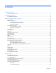
Server component identification Front panel components and LEDs Item Description 1 UID LED 2 Health LED 3 Flex 1 LED 4 Flex 2 LED 5 Flex 3 LED 6 Flex 4 LED 7 Power On/Standby button and system power LED 8 Hard drive bay 1 9 Hard drive bay 2 10 Server release lever 11 Server release lever button 12 Local I/O connector Server component identification 60
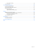
SAS and SATA hard drive LEDs Item Description 1 Fault/UID LED (amber/blue) 2 Online LED (green) SAS and SATA hard drive LED combinations Online/activity LED (green) Fault/UID LED (amber/blue) Interpretation On, off, or flashing Alternating amber and blue The drive has failed, or a predictive failure alert has been received for this drive; it also has been selected by a management application.
Online/activity LED (green) Fault/UID LED (amber/blue) Interpretation Off Steadily amber A critical fault condition has been identified for this drive, and the controller has placed it offline. Replace the drive as soon as possible. Off Amber, flashing regularly (1 Hz) A predictive failure alert has been received for this drive. Replace the drive as soon as possible. Off Off The drive is offline, a spare, or not configured as part of an array.
Item Description 15 Processor 1 16 System battery 17 SAS/SATA backplane power connector 18 Processor 2 The symbols correspond to the symbols located on the interconnect bays. For more information, see the HP ProLiant BL620c G7 Server Blade Installation Instructions that ship with the server blade. System maintenance switch The system maintenance switch (SW1) is an eight-position switch that is used for system configuration. The default position for all eight positions is Off.
5. Install the access panel ("Access panel" on page 25). 6. Install the server blade in the enclosure and power up the server blade. 7. Wait for the POST message that prompts you to change the switch setting: Maintenance switch detected in the "On" position. Power off the server and turn switch to the "Off" position. 8. Repeat steps 1 through 3. 9. Change position 6 of the system maintenance switch to off. 10. Repeat steps 5 and 6.
Cabling Using the HP c-Class Blade SUV Cable The HP c-Class Blade SUV Cable enables the user to perform server blade administration, configuration, and diagnostic procedures by connecting video and USB devices directly to the server blade. For SUV cable connectors, see "HP c-Class Blade SUV Cable (on page 67).
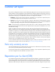
4. Connect a USB keyboard to the second USB connector. Item Description 1 Monitor 2 USB mouse 3 HP c-Class Blade SUV Cable 4 Video connector 5 Server blade 6 USB keyboard Accessing local media devices Use the following configuration when configuring a server blade or loading software updates and patches from a USB CD/DVD-ROM or a USB diskette. 1. Connect the SUV cable to the server blade. 2. Connect the video connector to a monitor. 3. Connect a USB hub to one USB connector. 4.
Item Description 1 Monitor 2 USB mouse 3 HP c-Class Blade SUV Cable 4 Server blade 5 USB hub 6 USB keyboard 7 USB CD/DVD-ROM drive or diskette drive HP c-Class Blade SUV Cable Item Connector Description 1 Workstation blade For connecting to the SUV connector on the Cabling 67
Item Connector Description 2 Video For connecting a video monitor 3 USB For connecting up to two USB devices 4 Serial For trained personnel to connect a null modem serial cable and perform advanced diagnostic procedures server blade front panel Cabling 68
Specifications Environmental specifications Specification Value — Temperature range* Operating 10°C to 35°C (50°F to 95°F) Non-operating -30°C to 60°C (-22°F to 140°F) Relative humidity (noncondensing)** — Operating 10% to 90% @ 28°C (82.4°F) Non-operating 5% to 95% @ 38.7°C (101.7°F) Altitude† — Operating 3050 m (10,000 ft) Non-operating 9144 m (30,000 ft) * The following temperature conditions and limitations apply: - All temperature ratings shown are for sea level.
Acronyms and abbreviations ACU Array Configuration Utility BBWC battery-backed write cache CSR Customer Self Repair DDR double data rate ESD electrostatic discharge FC Fibre Channel HBA host bus adapter HCA Host Channel Adapter IB InfiniBand iLO 3 Integrated Lights-Out 3 IML Integrated Management Log PCIe peripheral component interconnect express Acronyms and abbreviations 70
POST Power-On Self Test PSP ProLiant Support Pack QDR quad data rate RBSU ROM-Based Setup Utility RPM Red Hat Package Manager SAS serial attached SCSI SATA serial ATA SD Secure Digital SDHC Secure Digital High-Capacity SFF small form-factor SIM Systems Insight Manager SSD solid-state drive SUV serial, USB, video TPM trusted platform module Acronyms and abbreviations 71
UID unit identification USB universal serial bus Acronyms and abbreviations 72
Index front panel/hard drive cage assembly A access panel 16, 25 accessing a server blade with local KVM additional information 56 B batteries, replacing 52 battery 16, 52 battery pack, removing 34 battery-backed write cache (BBWC) BBWC (battery-backed write cache) buttons 60 C H 65, 66 hard drive blanks 16, 26 hard drive LEDs 61 hard drives 16, 26, 61 hard drives, determining status of 61 health LEDs 61 heatsink 36 heatsink blank 30 HP c-Class Blade SUV Cable 65, 67 HP Insight Diagnostics 22, 57 HP In
utilities, deployment processor tool 38, 44 processors 16, 38 V R RBSU (ROM-Based Setup Utility) recovering BBWC data 36 release button 54 removing the server blade 24 resources 56 resources, troubleshooting 56 ROM legacy USB support 58 ROM redundancy 64 ROM-Based Setup Utility (RBSU) 56 56 video connector 65, 67 video connector cabling 67 W warnings 22 56 S safety considerations 22 safety information 22 SAS drives 61 SAS hard drive LEDs 61 SATA hard drive 61 SATA hard drive LEDs 61 SD support 59