HP ProLiant BL660c Gen8 Server Blade Maintenance and Service Guide Abstract This guide describes identification and maintenance procedures, diagnostic tools, specifications and requirements for hardware components and software. This guide is for an experienced service technician.
© Copyright 2013, 2014 Hewlett-Packard Development Company, L.P. The information contained herein is subject to change without notice. The only warranties for HP products and services are set forth in the express warranty statements accompanying such products and services. Nothing herein should be construed as constituting an additional warranty. HP shall not be liable for technical or editorial errors or omissions contained herein. Microsoft® and Windows® are U.S.
Contents Customer self repair ...................................................................................................................... 5 Parts only warranty service ......................................................................................................................... 5 Illustrated parts catalog ............................................................................................................... 15 Server blade components ...........................................
Front panel components ........................................................................................................................... 57 Front panel LEDs and buttons .................................................................................................................... 57 Hot-plug drive LED definitions.................................................................................................................... 58 System board components .......................................
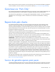
Customer self repair HP products are designed with many Customer Self Repair (CSR) parts to minimize repair time and allow for greater flexibility in performing defective parts replacement. If during the diagnosis period HP (or HP service providers or service partners) identifies that the repair can be accomplished by the use of a CSR part, HP will ship that part directly to you for replacement. There are two categories of CSR parts: • Mandatory—Parts for which customer self repair is mandatory.
Obligatoire - Pièces pour lesquelles la réparation par le client est obligatoire. Si vous demandez à HP de remplacer ces pièces, les coûts de déplacement et main d'œuvre du service vous seront facturés. Facultatif - Pièces pour lesquelles la réparation par le client est facultative. Ces pièces sont également conçues pour permettre au client d'effectuer lui-même la réparation.
In base alla disponibilità e alla località geografica, le parti CSR vengono spedite con consegna entro il giorno lavorativo seguente. La consegna nel giorno stesso o entro quattro ore è offerta con un supplemento di costo solo in alcune zone. In caso di necessità si può richiedere l'assistenza telefonica di un addetto del centro di supporto tecnico HP. Nel materiale fornito con una parte di ricambio CSR, HP specifica se il cliente deve restituire dei componenti.
defekte Teil nicht zurückschicken, kann HP Ihnen das Ersatzteil in Rechnung stellen. Im Falle von Customer Self Repair kommt HP für alle Kosten für die Lieferung und Rücksendung auf und bestimmt den Kurier-/Frachtdienst. Weitere Informationen über das HP Customer Self Repair Programm erhalten Sie von Ihrem Servicepartner vor Ort. Informationen über das CSR-Programm in Nordamerika finden Sie auf der HP Website unter (http://www.hp.com/go/selfrepair).
enviara el componente defectuoso requerido, HP podrá cobrarle por el de sustitución. En el caso de todas sustituciones que lleve a cabo el cliente, HP se hará cargo de todos los gastos de envío y devolución de componentes y escogerá la empresa de transporte que se utilice para dicho servicio. Para obtener más información acerca del programa de Reparaciones del propio cliente de HP, póngase en contacto con su proveedor de servicios local.
Neem contact op met een Service Partner voor meer informatie over het Customer Self Repair programma van HP. Informatie over Service Partners vindt u op de HP website (http://www.hp.com/go/selfrepair). Garantieservice "Parts Only" Het is mogelijk dat de HP garantie alleen de garantieservice "Parts Only" omvat. Volgens de bepalingen van de Parts Only garantieservice zal HP kosteloos vervangende onderdelen ter beschikking stellen.
No caso desse serviço, a substituição de peças CSR é obrigatória. Se desejar que a HP substitua essas peças, serão cobradas as despesas de transporte e mão-de-obra do serviço.
Customer self repair 12
Customer self repair 13
Customer self repair 14
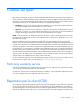
Illustrated parts catalog Server blade components Item Description Spare part number Customer self repair (on page 5) Mechanical components 1 Access panel 697849-001 Mandatory1 2 Drive blank (SFF) 670033-001 Mandatory1 3 DIMM baffle kit 697850-001 Mandatory1 a) DIMM baffle, right — — b) DIMM baffle, left with T-15 Torx screwdriver and DIMM tool c) DIMM baffle, center — — — — Mezzanine assembly — — a) Mezzanine connector 1 and 2 683822-001 Mandatory1 b) Mezzanine connector 3 69785
Item Description Spare part number Customer self repair (on page 5) a) Enclosure connector cover — — b) Accelerator Cache module retainer and guide pin assembly c) Mezzanine assembly retainer assembly — — — — d) Mezzanine assembly guide pins (2) — — e) T-15 system board screws (2) — — System components 6 7 Front panel/drive cage assembly with two drive backplane 683799-001 Mandatory1 boards Processors — — a) 2.00-GHz Intel Xeon E5-4603 processor** 687968-001 Optional2 b) 2.
Item 10 Description Spare part number Customer self repair (on page 5) e) 500-GB, SAS, SFF, 7,200-rpm, 6G* 653953-001 Mandatory1 f) 600-GB, SAS, SFF, 10,000-rpm, 6G* 653957-001 Mandatory1 g) 900-GB, SAS, SFF, 10,000-rpm, 6G* 653971-001 Mandatory1 h) 1-TB, SAS, SFF, 7,200-rpm, 6G* 653954-001 Mandatory1 i) 1-TB, SATA, SFF, 7,200-rpm, 6G* 656108-001 Mandatory1 Solid state drives* — a) 200-GB, SAS, SLC, SFF 653961-001 Mandatory1 b) 200-GB, SAS, MLC, SFF 658580-001 Mandatory1 c) 400-GB, SAS,
Item 13 14 Description Spare part number Customer self repair (on page 5) a) 512-MB, HP Smart Array P721M cache module 673609-001 Mandatory1 b) 2-GB, HP Smart Array P721M cache module for use with 673610-001 Mandatory1 the P721m mezzanine board* System boards — — a) System I/O board 683798-001 Optional2 b) System I/O board IVB* 747358-001 Optional2 Trusted Platform Module 505836-001 No3 Mezzanine and FlexibleLOM options 15 16 17 Controllers* — a) HP Fibre Channel 8 Gb LPe1205A Adapter 66
Item Description Spare part number Customer self repair (on page 5) a) Enclosure connector cover — — b) Cache module retainer with guide pin assembly — — c) Mezzanine assembly retainer assembly — — d) Mezzanine assembly guide pins (2) — — e) T-15 system board screws (2) — — *Not shown **Do not mix processors with different speeds or cache sizes. 1 Mandatory—Parts for which customer self repair is mandatory.
No: No—Algunos componentes no están diseñados para que puedan ser reparados por el usuario. Para que el usuario haga valer su garantía, HP pone como condición que un proveedor de servicios autorizado realice la sustitución de estos componentes. Dichos componentes se identifican con la palabra “No” en el catálogo ilustrado de componentes. 3 Mandatory: Verplicht—Onderdelen waarvoor Customer Self Repair verplicht is.
Removal and replacement procedures Required tools You need the following items for some procedures: • DIMM tool (provided on the DIMM baffle) • T-15 Torx screwdriver (provided on the DIMM baffle) • T-10 Torx screwdriver (not provided with the server blade) • HP Insight Diagnostics software ("HP Insight Diagnostics" on page 53) Safety considerations Before performing service procedures, review all the safety information.
CAUTION: When performing non-hot-plug operations, you must power down the server blade and/or the system. However, it may be necessary to leave the server blade powered up when performing other operations, such as hot-plug installations or troubleshooting. Symbols on equipment The following symbols may be placed on equipment to indicate the presence of potentially hazardous conditions. This symbol indicates the presence of hazardous energy circuits or electric shock hazards.
IMPORTANT: When the server blade is in standby mode, auxiliary power is still being provided to the system. Depending on the Onboard Administrator configuration, use one of the following methods to power down the server blade: • Press and release the Power On/Standby button. This method initiates a controlled shutdown of applications and the OS before the server blade enters standby mode.
3. Remove the server blade. 4. Place the server blade on a flat, level work surface. WARNING: To reduce the risk of personal injury from hot surfaces, allow the drives and the internal system components to cool before touching them. CAUTION: To prevent damage to electrical components, properly ground the server blade before beginning any installation procedure. Improper grounding can cause ESD. Access panel To remove the component: 1. Power down the server blade (on page 22). 2.
Drive blank Remove the component as indicated. To replace the component, squeeze the release latch and slide the drive blank into the bay until it clicks into place. Drive To remove the component: 1. Determine the status of the drive from the drive LED definitions ("Hot-plug drive LED definitions" on page 58). 2. Back up all server blade data on the drive. 3. Remove the drive.
1. Prepare the drive. 2. Install the drive. 3. Determine the status of the drive from the drive LED definitions ("Hot-plug drive LED definitions" on page 58). Enclosure connector covers To remove the component: 1. Place the server blade on a flat, level work surface.
2. Remove the enclosure connector covers. To replace the component, reverse the removal procedure. DIMM baffles CAUTION: To avoid damage to the server blade and the enclosure, install all DIMM baffles in the proper location after adding or replacing DIMMs. DIMM baffles that are missing or installed incorrectly can compromise server blade and enclosure cooling. The server blade contains three DIMM baffles. 1. Power down the server blade (on page 22). 2. Remove the server blade (on page 23). 3.
o Center DIMM baffle o Right DIMM baffle Removal and replacement procedures 28
o Left DIMM baffle To replace the component, reverse the removal procedure. DIMMs IMPORTANT: This server blade does not support mixing LRDIMMs or RDIMMs. Attempting to mix any combination of these DIMMs can cause the server to halt during BIOS initialization. To identify the DIMMs installed in the server blade, see "DIMM identification (on page 61)." To remove the component: 1. Power down the server blade (on page 22). 2. Remove the server blade (on page 23). 3.
7. Remove the DIMM and then use the DIMM tool to close the DIMM slot. To replace the component: 1. Use the DIMM tool to open the DIMM slot. 2. Install the DIMM. 3. Install all DIMM baffles ("DIMM baffles" on page 27). 4. Attach the FBWC capacitor pack cabling (on page 64), if necessary. 5. Install the access panel ("Access panel" on page 24). 6. To configure the memory mode, use RBSU ("HP ROM-Based Setup Utility" on page 53). Mezzanine assembly To remove the component: 1.
2. Remove the server blade (on page 23). 3. Remove the access panel ("Access panel" on page 24). 4. Remove the mezzanine assembly from the server blade. To replace the component: 1. Install the access panel ("Access panel" on page 24). 2. Align the mezzanine assembly with the guide pins on the system board, and then install the mezzanine assembly on the system board. 3. Press down firmly on the mezzanine assembly handles, and then close the mezzanine assembly latch.
Mezzanine card To remove the component: 1. Power down the server blade (on page 22). 2. Remove the server blade (on page 23). 3. Remove the access panel ("Access panel" on page 24). 4. Remove the mezzanine assembly ("Mezzanine assembly" on page 30). 5. Remove the mezzanine card from the mezzanine assembly. To replace the component: 1. Align the mezzanine card with the guide pins on the mezzanine assembly.
2. Install the mezzanine card in the mezzanine assembly, and then tighten the mezzanine card screws to secure the card to the mezzanine assembly. 3. Align the mezzanine assembly with the guide pins on the system board, and then install the mezzanine assembly on the system board. 4. Press down firmly on the mezzanine assembly handles, and then close the mezzanine assembly latch. 5. Install the access panel ("Access panel" on page 24). FlexibleLOM To remove the component: 1.
5. Use the FlexibleLOM handle to remove the FlexibleLOM from the system board. To replace the component: 1. Align and install the FlexibleLOM. Press down on the handle to seat the FlexibleLOM on the system board. 2. Install the mezzanine assembly ("Mezzanine assembly" on page 30). 3. Install the access panel ("Access panel" on page 24).
Removing the FBWC capacitor packs To remove the component: 1. Power down the server blade (on page 22). 2. Remove the server blade (on page 23). 3. Remove the access panel ("Access panel" on page 24). 4. Locate the capacitor pack on the drive cage. For more information, see "FBWC capacitor pack cabling (on page 64)." 5. Remove the capacitor pack from the carrier. Removing the cache module To remove the component: 1. Power down the server blade (on page 22). 2.
5. Remove the cache module. Recovering data from the FBWC If the server blade fails, use the following procedure to recover data temporarily stored in the FBWC. CAUTION: Before starting this procedure, read the information about protecting against electrostatic discharge ("Preventing electrostatic discharge" on page 21). 1. Set up a recovery server blade station using an identical server blade model. Do not install any internal drives or FBWC in this server blade. (HP recommends this option.) 2.
Front panel/drive cage assembly To remove the component: 1. Power down the server blade (on page 22). 2. Remove the server blade (on page 23). 3. Remove the access panel ("Access panel" on page 24). 4. Remove all drives ("Drive" on page 25). 5. Remove all DIMM baffles ("DIMM baffles" on page 27). 6. Remove all FBWC capacitor packs ("Removing the FBWC capacitor packs" on page 35). 7. Disconnect the two signal cables and one power cable from each SAS backplane. 8.
System battery If the server blade no longer automatically displays the correct date and time, then replace the battery that provides power to the real-time clock. Under normal use, battery life is 5 to 10 years. WARNING: The computer contains an internal lithium manganese dioxide, a vanadium pentoxide, or an alkaline battery pack. A risk of fire and burns exists if the battery pack is not properly handled. To reduce the risk of personal injury: • • • • Do not attempt to recharge the battery.
1. Power down the server blade (on page 22). 2. Remove the server blade (on page 23). 3. Remove the access panel ("Access panel" on page 24). 4. Disconnect and remove FBWC capacitor pack cabling, if installed ("Removing the FBWC capacitor packs" on page 35). 5. Remove all DIMM baffles ("DIMM baffles" on page 27). 6. Remove the front panel/drive cage assembly ("Front panel/drive cage assembly" on page 37). 7. Remove the heatsink. To replace the component: 1.
CAUTION: To avoid damage to the system board, processor socket, and screws, do not overtighten the heatsink screws. Use the wrench supplied with the system to reduce the possibility of overtightening the screws. 3. Align and install the heatsink. Alternate tightening the screws until the heatsink is seated properly. 4. Install the front panel/drive cage assembly ("Front panel/drive cage assembly" on page 37). 5. Install all DIMM baffles ("DIMM baffles" on page 27). 6.
4. Remove the access panel ("Access panel" on page 24). 5. Remove all drives ("Drive" on page 25). 6. Remove all FBWC capacitor packs ("Removing the FBWC capacitor packs" on page 35). 7. Remove all DIMM baffles ("DIMM baffles" on page 27). 8. Disconnect all cables from the drive backplane. For more information, see "Cabling (on page 64)." 9. Remove the front panel/drive cage assembly ("Front panel/drive cage assembly" on page 37). 10. Remove the heatsink ("Heatsink" on page 38). 11.
To replace the component: CAUTION: To avoid damage to the system board, processor socket, and screws, do not overtighten the heatsink screws. Use the wrench supplied with the system to reduce the possibility of overtightening the screws. 1. Install the processor. Verify that the processor is fully seated in the processor retaining bracket by visually inspecting the processor installation guides on either side of the processor. THE PINS ON THE SYSTEM BOARD ARE VERY FRAGILE AND EASILY DAMAGED.
3. Press and hold the processor retaining bracket in place, and then close each processor locking lever. Press only in the area indicated on the processor retaining bracket. 4. Align and install the heatsink. Alternate tightening the screws until the heatsink is seated properly. 5. Install all DIMM baffles ("DIMM baffles" on page 27). 6. Install the front panel/drive cage assembly ("Front panel/drive cage assembly" on page 37). 7. Disconnect all cables from the drive backplane.
System board CAUTION: When returning a damaged system board to HP, always install all processor socket covers to prevent damage to the processor sockets and system board. To remove the component: 1. Power down the server blade (on page 22). 2. Remove the server blade (on page 23). 3. Remove the access panel ("Access panel" on page 24). 4. Remove all hard drives ("Drive" on page 25). 5. Remove all hard drive blanks ("Drive blank" on page 25). 6.
16. Remove the processor from the processor retaining bracket. CAUTION: To avoid damage to the processor, do not touch the bottom of the processor, especially the contact area. 17. Install the processor socket protective cover in each processor socket. 18. Remove the system board from the base pan. 19. Remove the enclosure connector covers from the new system board and install the enclosure connector covers on the damaged system board.
2. Install the system board into the base pan. IMPORTANT: Install all components in the same configuration prior to removing the system board. 3. Install the FlexibleLOM ("FlexibleLOM" on page 33). 4. Install the mezzanine assembly ("Mezzanine assembly" on page 30). 5. Open each of the processor locking levers in the order indicated, and then open the processor retaining bracket.
6. Remove the clear processor socket cover. Retain the processor socket cover for future use. 7. Install the processor. Verify that the processor is fully seated in the processor retaining bracket by visually inspecting the processor installation guides on either side of the processor. THE PINS ON THE SYSTEM BOARD ARE VERY FRAGILE AND EASILY DAMAGED. CAUTION: THE PINS ON THE SYSTEM BOARD ARE VERY FRAGILE AND EASILY DAMAGED.
CAUTION: Do not press down on the processor. Pressing down on the processor may cause damage to the processor socket and the system board. Press only in the area indicated on the processor retaining bracket. 9. Press and hold the processor retaining bracket in place, and then close each processor locking lever. Press only in the area indicated on the processor retaining bracket. 10. Install the processor socket cover onto the processor socket of the failed system board. 11.
16. Install all DIMM baffles ("DIMM baffles" on page 27). 17. Install and route the cables for all capacitor packs. For more information on routing the cables, see "FBWC capacitor pack cabling (on page 64)." 18. Install the hard drives ("Drive" on page 25). 19. Install the hard drive blanks ("Drive blank" on page 25). 20. Install the access panel ("Access panel" on page 24). 21. Install the server blade.
12. Disengage the three system board thumbscrews. Slide the system board approximately 1.27 cm (0.50 inches) towards the rear of the server and lift the system board from the base pan. 13. Remove the server blade release lever.
To replace the component: 1. Install the server blade release lever. 2. Align the system board, and then slide it into place inside the base pan. IMPORTANT: Install all components in the same configuration prior to removing the system board. 3. Install the front panel/drive cage assembly ("Front panel/drive cage assembly" on page 37). 4. Connect all cables to the hard drive backplane. For more information, see "Cabling (on page 64)." 5. Install all DIMMs ("DIMMs" on page 29). 6.
10. Install the access panel ("Access panel" on page 24). HP Trusted Platform Module The TPM is not a customer-removable part. CAUTION: Any attempt to remove an installed TPM from the system board breaks or disfigures the TPM security rivet. Upon locating a broken or disfigured rivet on an installed TPM, administrators should consider the system compromised and take appropriate measures to ensure the integrity of the system data.
Diagnostic tools HP ROM-Based Setup Utility RBSU is a configuration utility embedded in HP ProLiant servers that performs a wide range of configuration activities that can include the following: • Configuring system devices and installed options • Enabling and disabling system features • Displaying system information • Selecting the primary boot controller • Configuring memory options • Language selection For more information on RBSU, see the HP ROM-Based Setup Utility User Guide on the Documen
HP Insight Diagnostics Offline Edition performs various in-depth system and component testing while the OS is not running. To run this utility, boot the server blade using Intelligent Provisioning. HP Insight Diagnostics Online Edition is a web-based application that captures system configuration and other related data needed for effective server blade management. Available in Microsoft Windows and Linux versions, the utility helps to ensure proper system operation.
The data that is collected is managed according to the HP Data Privacy policy. For more information see the HP website (http://www.hp.com/go/privacy). The Active Health System log, in conjunction with the system monitoring provided by Agentless Management or SNMP Pass-thru, provides continuous monitoring of hardware and configuration changes, system status, and service alerts for various server components. The Agentless Management Service is available in the SPP, which is a disk image (.
Internal USB functionality An internal USB connector is available for use with security key devices and USB drive keys. This solution provides for use of a permanent USB key installed in the internal connector, avoiding issues of clearance on the front of the rack and physical access to secure data. External USB functionality HP provides external USB support to enable local connection of USB devices for server blade administration, configuration, and diagnostic procedures.
Component identification Front panel components Item Description 1 HP c-Class Blade SUV cable connector (behind the serial label pull tab) 2 Serial label pull tab 3 Drive bay 1 4 Drive bay 2 5 Server blade release lever 6 Server blade release button Front panel LEDs and buttons Item Description Status 1 Health status LED bar Solid Green = Normal (System is powered on.) Flashing Green = Power On/Standby Button service is being initialized.
Item Description 4 FlexibleLOM LED Status Green = Network linked Flashing Green = Network activity Off = No link or activity Hot-plug drive LED definitions Item LED Status Definition 1 Locate Solid blue The drive is being identified by a host application. Flashing blue The drive carrier firmware is being updated or requires an update. Rotating green Drive activity Off No drive activity Solid white Do not remove the drive.
System board components Item Description 1 HP c-Class Blade SUV cable connector 2 Processor 3 DIMM slots (8) 3 Processor socket 3 (populated) 4 Processor 1 DIMM slots (8) 5 Processor socket 1 (populated) 6 System board thumbscrew 7 System maintenance switch 8 TPM connector 9 Mezzanine assembly guide pins 10 Enclosure connector 11 Mezzanine connector 1 (Type A mezzanine only) 12 Mezzanine connector 2 (Type A or Type B mezzanine) 13 FlexibleLOM 2 connectors (2) 14 Internal USB co
Mezzanine connector definitions A PCIe x8 mezzanine connector supports x16 cards at up to x8 speeds. Item PCIe Mezzanine connector 1 x8, Type A mezzanine card only Mezzanine connector 2 x16, Type A or B mezzanine card Mezzanine connector 3 x16, Type A or B mezzanine card DIMM slot locations DIMM slots are numbered sequentially (1 through 8) for each processor. The supported AMP modes use the alpha assignments for population order and the slot numbers designate the DIMM slot ID for spare replacement.
DIMM identification To determine DIMM characteristics, use the label attached to the DIMM and the following illustration and table. Item Description Definition 1 Size — 2 Rank 1R 2R 3R 4R 3 Data width x4 = 4-bit x8 = 8-bit 4 Voltage rating L = Low voltage (1.35V) U = Ultra low voltage (1.
Tool locations Item Description 1 DIMM tool 2 T-15 Torx screwdriver HP c-Class Blade SUV Cable Item Connector Description 1 Server blade For connecting to the SUV connector on the server blade front panel 2 Video For connecting a video monitor 3 USB For connecting up to two USB devices Component identification 62
Item Connector Description 4 Serial For trained personnel to connect a null modem serial cable and perform advanced diagnostic procedures Component identification 63
Cabling Cabling overview This section provides guidelines that help you make informed decisions about cabling the server and hardware options to optimize performance.
• FBWC capacitor pack cable to the cache module option • FBWC capacitor pack cabling to the mezzanine 3 connector option For capacitor pack and cabling instructions, see "Removing the FBWC capacitor packs (on page 35).
Drive cabling Using the HP c-Class Blade SUV Cable The HP c-Class Blade SUV Cable enables the user to perform server blade administration, configuration, and diagnostic procedures by connecting video and USB devices directly to the server blade. For SUV cable connectors, see "HP c-Class Blade SUV Cable (on page 62).
3. Connect a USB mouse to one USB connector. 4. Connect a USB keyboard to the second USB connector. Item Description 1 Monitor 2 USB mouse 3 USB keyboard 4 HP c-Class Blade SUV Cable Accessing local media devices Use the following configuration when configuring a server blade or loading software updates and patches from a USB CD/DVD-ROM. Use a USB hub when connecting a USB CD-ROM drive to the server blade. The USB hub provides additional connections. 1.
o USB mouse Item Description 1 Monitor 2 USB CD/DVD-ROM drive 3 USB keyboard 4 USB hub 5 USB mouse 6 HP c-Class Blade SUV Cable Cabling 68
Troubleshooting Troubleshooting resources The HP ProLiant Gen8 Troubleshooting Guide, Volume I: Troubleshooting provides procedures for resolving common problems and comprehensive courses of action for fault isolation and identification, issue resolution, and software maintenance on ProLiant servers and server blades. To view the guide, select a language: • English (http://www.hp.com/support/ProLiant_TSG_v1_en) • French (http://www.hp.com/support/ProLiant_TSG_v1_fr) • Spanish (http://www.hp.
Specifications Environmental specifications Specification Value — Temperature range* Operating 10°C to 35°C (50°F to 95°F) Non-operating -30°C to 60°C (-22°F to 140°F) Relative humidity (noncondensing)** — Operating 10% to 90% @ 28°C (82.4°F) Non-operating 5% to 95% @ 38.7°C (101.7°F) Altitude† — Operating 3050 m (10,000 ft) Non-operating 9144 m (30,000 ft) * The following temperature conditions and limitations apply: - All temperature ratings shown are for sea level.
Acronyms and abbreviations AMP Advanced Memory Protection CSR Customer Self Repair ESD electrostatic discharge FBWC flash-backed write cache IML Integrated Management Log KVM keyboard, video, and mouse LOM LAN on Motherboard LRDIMM load reduced dual in-line memory module NVRAM nonvolatile memory PCIe Peripheral Component Interconnect Express POST Power-On Self Test PSP HP ProLiant Support Pack Acronyms and abbreviations 71
RBSU ROM-Based Setup Utility RDIMM registered dual in-line memory module SAS serial attached SCSI SATA serial ATA SD Secure Digital SIM Systems Insight Manager SUV serial, USB, video TPM Trusted Platform Module UDIMM unregistered dual in-line memory module USB universal serial bus Acronyms and abbreviations 72
Documentation feedback HP is committed to providing documentation that meets your needs. To help us improve the documentation, send any errors, suggestions, or comments to Documentation Feedback (mailto:docsfeedback@hp.com). Include the document title and part number, version number, or the URL when submitting your feedback.
Index A access panel 24 Active Health System 54 B baffles 27 batteries, replacing 38 battery 38, 59 buttons 21, 57 buttons, front panel 57 C cables 64, 66, 67 cabling 64, 66 cabling, drive 66 cabling, hard drive 66 cabling, hard drive backplane 66 cache module 35 cache module, removing 35 cautions 21 components 15, 21, 32, 57 components, identification 15, 57 components, mechanical 15 connectors 57 CSR (customer self repair) 5 customer self repair (CSR) 5 D data recovery 36 definitions 58 diagnosing prob
health status LED bar 57 heatsink 38 heatsink blank 38 HP c-Class Blade SUV Cable 62, 66 HP Insight Diagnostics 21, 53, 54 HP Insight Diagnostics survey functionality 54 HP technical support 5 I identifying components 57 illustrated parts catalog 15 iLO (Integrated Lights-Out) 54, 55 IML (Integrated Management Log) 55 Insight Diagnostics 21, 53, 54 Integrated Lights-Out (iLO) 55 Integrated Management Log (IML) 55 internal USB connector 59 internal USB functionality 56 L LED, health 57 LED, power button 57
symbols on equipment 22 system board battery 38, 59 system board components 59 system board replacement 44 system board thumbscrews 59 system components 57 system maintenance switch 59 T T-15 Torx screwdriver 21, 62 technical support 5 tool locations 62 tool, DIMM 21, 62 tools 21, 62 Torx screwdriver 21, 62 TPM (Trusted Platform Module) 52 TPM connector 59 troubleshooting 69 troubleshooting resources 69 Trusted Platform Module (TPM) 52 U USB (universal serial bus) 55, 56 USB connector 62 USB devices 66, 6