
HP ProLiant BL680c G7 Server Blade Maintenance and Service Guide
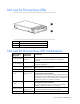
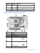
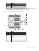
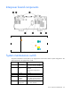
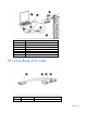
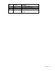
Table Of Contents
- HP ProLiant BL680c G7 Server Blade Maintenance and Service Guide
- Abstract
- Notice
- Contents
- Customer self repair
- Illustrated parts catalog
- Removal and replacement procedures
- Required tools
- Safety considerations
- Server blade preparation
- Access panel (A-side)
- Access panel (B-side)
- Left DIMM baffle
- Right DIMM baffle
- DIMM (A-side)
- DIMM (B-side)
- Mezzanine connector cover (A-side)
- Mezzanine connector cover (B-side)
- Heatsink blank
- Mezzanine card (A-side)
- Mezzanine card (B-side)
- Hard drive blank
- Hard drive
- Front panel/hard drive cage assembly (A-side)
- Front panel/hard drive cage assembly (B-side)
- Battery-backed write cache procedures
- Interposer board
- Heatsink (A-side)
- Heatsink (B-side)
- Processor (A-side)
- Processor (B-side)
- System board (A-side)
- System board (B-side)
- System battery
- Server blade release lever
- Release button
- HP Trusted Platform Module
- Diagnostic tools
- Server component identification
- Cabling
- Specifications
- Acronyms and abbreviations
- Index
Server component identification 95
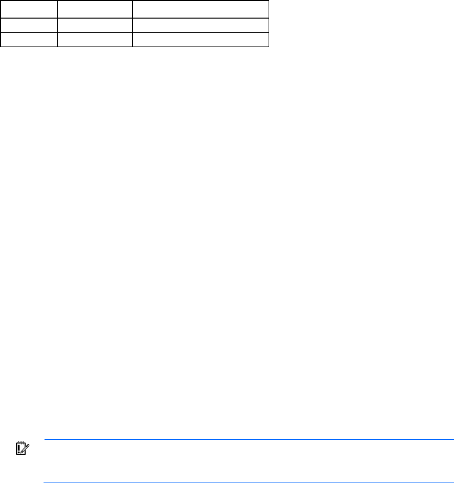
Position Description Function
S7
Reserved Reserved
S8
Reserved Reserved
System maintenance switch procedures
When you perform troubleshooting steps, this guide may instruct you to perform the following procedures:
• Clear the system configuration ("Clearing the system configuration" on page 95).
• Access the redundant ROM ("Accessing the redundant ROM" on page 95).
To complete these procedures, you must change physical settings on the system maintenance switch.
Clearing the system configuration
RBSU can be used to restore the factory default configuration. For more information, see "HP ROM-Based
Setup Utility (on page 86)." If the system is unable to boot into RBSU, use the following steps to clear the
system configuration:
1. Power down the server blade (on page 28).
2. Remove the server blade (on page 29).
3. Remove the access panel.
4. Change position 6 of the system maintenance switch to on.
5. Install the access panel.
6. Install the server blade in the enclosure and power up the server blade.
7. Wait for the POST message that prompts you to change the switch setting:
Maintenance switch detected in the "On" position.
Power off the server and turn switch to the "Off" position.
8. Repeat steps 1 through 3.
9. Change position 6 of the system maintenance switch to off.
10. Repeat steps 5 and 6.
IMPORTANT: When the server blade boots after NVRAM is cleared, a delay of up to 2 minutes
is normal. During this delay, the system appears non-functional. Do not attempt any procedures
during the delay.
Accessing the redundant ROM
If the system ROM is corrupted, the system automatically switches to the redundant ROM in most cases. If the
system does not automatically switch to the redundant ROM, perform the following steps:
1. Power down the server blade (on page 28).
2. Remove the server blade (on page 29).
3. Remove the access panel.
4. Change positions 1, 5, and 6 of the system maintenance switch to on.
5. Install the access panel.
6. Install the server blade in the enclosure and power up the server blade.