HP ProLiant BL685c Generation 5 Server Blade User Guide Part Number 457431-001 October 2007 (First Edition)
© Copyright 2007 Hewlett-Packard Development Company, L.P. The information contained herein is subject to change without notice. The only warranties for HP products and services are set forth in the express warranty statements accompanying such products and services. Nothing herein should be construed as constituting an additional warranty. HP shall not be liable for technical or editorial errors or omissions contained herein. Microsoft, and Windows are U.S. registered trademarks of Microsoft Corporation.
Contents Component identification ............................................................................................................... 6 Front panel components ............................................................................................................................. 6 Front panel LEDs ....................................................................................................................................... 7 SAS and SATA hard drive LEDs.............................
Accessing a server blade with local KVM ......................................................................................... 40 Accessing local media devices ........................................................................................................ 40 Software and configuration utilities ............................................................................................... 42 Server blade deployment tools .........................................................................
Troubleshooting flowcharts ....................................................................................................................... 63 Start diagnosis flowchart ................................................................................................................ 64 General diagnosis flowchart ........................................................................................................... 65 Server blade power-on problems flowchart ........................................
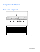
Component identification Front panel components Item Description 1 Hard drive bay 2 2 Server blade handle 3 Server blade handle release button 4 Serial pull tab 5 Hard drive bay 1 6 Local I/O cable connector* 7 Power On/Standby button * The local I/O cable connector is used with the local I/O cable to perform some server blade configuration and diagnostic procedures.
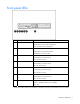
Front panel LEDs Item Description Status 1 UID LED Blue = Identified Blue flashing = Active remote management Off = No active remote management 2 Health LED Green = Normal operation Amber flashing = Degraded condition Red flashing = Critical condition 3 NIC 1 LED* Green = Network linked Green flashing = Network activity Off = No link or activity 4 NIC 2 LED* Green = Network linked Green flashing = Network activity Off = No link or activity 5 NIC 3 LED* Green = Network linked Green flashing
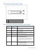
SAS and SATA hard drive LEDs Item Description 1 Fault/UID LED (amber/blue) 2 Online LED (green) SAS and SATA hard drive LED combinations Online/activity LED (green) Fault/UID LED (amber/blue) Interpretation On, off, or flashing Alternating amber and blue The drive has failed, or a predictive failure alert has been received for this drive; it also has been selected by a management application.
Online/activity LED (green) Fault/UID LED (amber/blue) Interpretation Flashing irregularly Amber, flashing regularly (1 Hz) The drive is active, but a predictive failure alert has been received for this drive. Replace the drive as soon as possible. Flashing irregularly Off The drive is active, and it is operating normally. Off Steadily amber A critical fault condition has been identified for this drive, and the controller has placed it offline. Replace the drive as soon as possible.
Item Description 13 Enclosure connector 2 14 System board thumbscrew 15 Embedded NIC 16 Embedded NIC 17 Smart Array E200i cache module (under mezzanine card 3) 18 SAS cable 19 Processor socket 1 (populated) 20 DIMM slots (Processor 1 memory banks A and B) 21 System battery 22 DIMM slots (Processor 3 memory banks E and F) 23 Processor socket 3 24 System board thumbscrew 25 System maintenance switch (SW2) 26 Hard drive backplane connector The symbols correspond to the symbols loc
DIMM slots For installation guidelines and population order, see "Memory option (on page 33)." System maintenance switch Position Function Default 1* iLO 2 security override Off 2 Configuration lock Off 3 Reserved Off 4 Reserved Off 5* Password disabled Off 6* Reset configuration Off 7 Reserved Off 8 Reserved Off *To access redundant ROM, set S1, S5, and S6 to ON.
Clearing the system configuration RBSU can be used to restore the factory default configuration. For more information, see "HP ROM-Based Setup Utility (on page 49)." If the system is unable to boot into RBSU, use the following steps to clear the system configuration: 1. Power down the server blade (on page 14). 2. Remove the server blade (on page 15). 3. Remove the access panel (on page 15). 4. Change position 6 of the system maintenance switch to on. 5. Install the access panel (on page 16). 6.
Local I/O cable Item Connector Description 1 Server blade For connecting to the local I/O cable connector on the server blade front panel 2 Video For connecting a video monitor 3 USB For connecting up to two USB devices 4 Serial For trained personnel to connect a null modem serial cable and perform advanced diagnostic procedures Component identification 13
Operations Power up the server blade The Onboard Administrator initiates an automatic power-up sequence when the server blade is installed. If the default setting is changed, use one of the following methods to power up the server blade: • Use a virtual power button selection through iLO 2. • Press and release the Power On/Standby button. When the server blade goes from the standby mode to the full power mode, the system power LED changes from amber to green.
Remove the server blade 1. Identify the proper server blade. 2. Power down the server blade (on page 14). 3. Remove the server blade. 4. Place the server blade on a flat, level work surface. WARNING: To reduce the risk of personal injury from hot surfaces, allow the drives and the internal system components to cool before touching them. CAUTION: To prevent damage to electrical components, properly ground the server blade before beginning any installation procedure. Improper grounding can cause ESD.
Install the access panel 1. Place the access panel on top of the server blade with the hood latch open. Allow the panel to extend past the rear of the server blade approximately 0.8 cm (0.2 in). 2. Engage the anchoring pin with the corresponding hole in the latch. 3. Push down on the hood latch. The access panel slides to a closed position.
o Install DIMM baffles for processor 1 and 3 memory banks with the R toward the front of the server blade. o Install DIMM baffles for processor 2 and 4 memory banks with the L toward the front of the server blade. 2. Install the access panel (on page 16). 3. Install the server blade ("Installing a server blade" on page 19).
Setup Overview Installation of a server blade requires the following steps: 1. Install and configure an HP BladeSystem c-Class enclosure. 2. Install any server blade options. 3. Install interconnect modules in the enclosure. 4. Connect the interconnect modules to the network. 5. Install a server blade. 6. Complete the server blade configuration. Installing an HP BladeSystem c-Class enclosure Before performing any server blade-specific procedures, install an HP BladeSystem c-Class enclosure.
Interconnect device mapping To support network connections for specific signals, install an interconnect module in the bay corresponding to the embedded NIC or mezzanine signals.
For detailed information on the c7000 or other BladeSystem enclosures, see the appropriate enclosure setup guide or server blade user guide. Enclosure documentation is located at the HP website (http://h71028.www7.hp.com/enterprise/cache/80316-0-0-0-121.html). Server blade documentation is located at the HP website (http://h18004.www1.hp.com/products/servers/platforms/). To install a server blade: 1. Remove the blank. 2. Remove the three adjacent blanks. 3.
4. Push the device bay shelf back until it stops, lift the right side slightly to disengage the two tabs from the divider wall, and then rotate the right edge downward (clockwise). 5. Lift the left side of the device bay shelf to disengage the three tabs from the divider wall, and then remove it from the enclosure.
6. Remove the connector covers. 7. Prepare the server blade for installation.
8. Install the server blade. CAUTION: To prevent improper cooling and thermal damage, do not operate the server blade or the enclosure unless all hard drive and device bays are populated with either a component or a blank. 9. Install blanks in any empty bays: a. Locate the coupler plate that ships with the server blade. b. Install the coupler plate on top of the blank, and then slide the coupler plate forward until it locks into place.
c. Install the second blank onto the tabs on the coupler plate, and then slide the second blank back until it locks into place. d. Install the full-height blank into the device bay. Connecting to the network To connect the HP BladeSystem to a network, each enclosure must be configured with network interconnect devices to manage signals between the server blades and the external network.
Hardware options installation Introduction If more than one option is being installed, read the installation instructions for all the hardware options and identify similar steps to streamline the installation process. WARNING: To reduce the risk of personal injury from hot surfaces, allow the drives and the internal system components to cool before touching them. CAUTION: To prevent damage to electrical components, properly ground the server before beginning any installation procedure.
2. Prepare the hard drive. 3. Install the hard drive. 4. Determine the status of the hard drive from the hot-plug hard drive LEDs ("SAS and SATA hard drive LEDs" on page 8). 5. Resume normal server blade operations. Processor option WARNING: To reduce the risk of personal injury from hot surfaces, allow the drives and the internal system components to cool before touching them.
CAUTION: To avoid damage to the system board: • Do not touch the processor socket contacts. • Always install the processor socket cover after removing the processor from the socket. • Do not tilt or slide the processor when lowering the processor into the socket. CAUTION: To avoid damage to the processor: • Handle the processor only by the edges. • Do not touch the bottom of the processor, especially the contact area.
CAUTION: The pins on the processor socket are very fragile. Any damage to them may require replacing the system board. 5. Remove the processor socket protective cover. Retain the cover for future use. CAUTION: Failure to completely open the processor retaining latch prevents the processor from seating during installation, leading to hardware damage. 6. Open the processor retaining latch and the processor socket retaining bracket.
7. If the processor has separated from the installation tool, carefully re-insert the processor in the tool. 8. Align the processor installation tool with the socket and install the processor. CAUTION: The processor is designed to fit one way into the socket. Use the alignment guides on the processor and socket to properly align the processor with the socket.
9. Press down firmly until the processor installation tool clicks and separates from the processor, and then remove the processor installation tool. 10. Close the processor retaining bracket and the processor retaining latch.
11. Remove the thermal interface protective cover from the heatsink. IMPORTANT: Do not install the air baffles on heatsinks for processors 3 and 4. 12. If the heatsink will be installed on processor 1 or 2, expose the adhesive and apply the air baffles to the side of the heatsink that will face the center of the server. 13.
o Processor 3 or 4 o Processor 1 or 2 CAUTION: Heatsink retaining screws should be tightened in diagonally opposite pairs (in an "X" pattern). 14.
o Processor 3 or 4 o Processor 1 or 2 15. Repeat these steps for the second processor and heatsink. 16. Install the access panel (on page 16). 17. Install the server blade ("Installing a server blade" on page 19). 18. Power up the server blade (on page 14). Memory option You can expand server memory by installing PC2-5300 Registered DDR2 SDRAM DIMMs. The server supports up to 64 GB of memory using 16 4-GB DIMMs (four DIMMs per processor).
For DIMM slot locations and bank assignments, see "DIMM slots (on page 11)." Advanced ECC memory Advanced ECC memory is the default memory protection mode for this server blade. In Advanced ECC, the server blade is protected against correctable memory errors. The server blade provides notification if the level of correctable errors exceeds a pre-defined threshold rate. The server blade does not fail because of correctable memory errors.
2. Remove the server blade (on page 15). 3. Remove the access panel (on page 15). 4. Remove the DIMM baffle. 5. Open the DIMM slot latches. 6. Install the DIMM. 7. Install the DIMM baffle (on page 16). 8. Install the access panel (on page 16). 9. Install the server blade ("Installing a server blade" on page 19). Mezzanine card option Optional mezzanine cards enable network connectivity and provide Fibre Channel support. For mezzanine card locations, see "System board components (on page 9).
4. Remove the mezzanine connector cover. Retain the cover for future use. 5. Install the mezzanine card. Press down above the connector to seat the board. 6. Install the access panel (on page 16). 7. Install the server blade ("Installing a server blade" on page 19). 8. Power up the server blade (on page 14). HP Smart Array E200i Controller battery pack option The optional BBWC enabler provides the system with a means for storing and saving data in the event of an unexpected system shutdown.
CAUTION: To prevent a server blade malfunction or damage to the equipment, do not add or remove the battery pack while an array capacity expansion, RAID level migration, or stripe size migration is in progress. CAUTION: After the server blade is powered down, wait 15 seconds and then check the amber LED before removing the battery from the cache module. If the amber LED flashes after 15 seconds, do not remove the battery from the cache module.
6. Install the Smart Array E200i battery pack on the new cache module provided in the option kit. 7. Install the new Smart Array E200i cache module. 8. Install mezzanine card 3, if necessary. 9. Install the access panel (on page 16). 10. Install the server blade ("Installing a server blade" on page 19). 11. Power up the server blade (on page 14).
Cabling SAS cable routing Using the local I/O cable The local I/O cable enables the user to perform server blade administration, configuration, and diagnostic procedures by connecting video and USB devices directly to the server blade. For local I/O cable connectors, see "Local I/O cable (on page 13).
Accessing a server blade with local KVM CAUTION: Before disconnecting the local I/O cable from the connector, always squeeze the release buttons on the sides of the connector. Failure to do so can result in damage to the equipment. NOTE: For this configuration, a USB hub is not necessary. To connect additional devices, use a USB hub. 1. Connect the local I/O cable to the server blade. 2. Connect the video connector to a monitor. 3. Connect a USB mouse to one USB connector. 4.
4. Connect the following to the USB hub: o USB CD/DVD-ROM drive o USB keyboard o USB mouse o USB diskette drive NOTE: Use a USB hub when connecting a USB diskette drive and/or USB CD-ROM drive to the server blade. The USB hub provides additional connections.
Software and configuration utilities Server blade deployment tools RBSU requirement for Linux deployment To properly install some versions of the Linux x64 operating system, the Linux x64 HPET Workaround selection in RBSU must be enabled. If this step is not performed, a kernel panic can occur during boot.
HP BladeSystem c-Class Advanced management iLO 2 is a standard component of ProLiant c-Class server blades that provides server health and remote server blade manageability. Its features are accessed from a network client device using a supported web browser. In addition to other features, iLO 2 provides keyboard, mouse, and video (text and graphics) capability for a server blade, regardless of the state of the host OS or host server blade.
be designated for PXE in RBSU. For NIC connector locations, refer to the documentation included with the server blade. NOTE: Actual NIC numeration depends on several factors, including the OS installed on the server blade. To deploy an OS to multiple server blades, install a PXE deployment server on a network. Deployment infrastructure IMPORTANT: To connect to a network with a Pass-Thru module, always connect the Pass-Thru module to a network device that supports Gigabit speed.
• o 10-Mb/s network adapter o CD-ROM drive Windows® repository server (Windows® or Linux deployment) o Windows® 2000 or Windows Server™ 2003 OS installed o Network connection o CD-ROM drive o 1.5 GB of available disk space o TCP/IP networking and an IP address compatible with one of the following: the iLO 2 Diagnostic Port IP address or an assigned DHCP or static IP address o CD-ROM drive and/or diskette drive o Any of the following Java™ Runtime Environment versions: 1.3.1_02 1.3.1_07 1.
A number of third-party PXE deployment tools are available for Windows® and Linux. For additional information, refer to the HP website (ftp://ftp.compaq.com/pub/products/servers/management/pxe_wp.pdf). HP ProLiant Essentials Rapid Deployment Pack NOTE: To deploy server blades in an existing server blade enclosure, always use the most recent version of RDP available at the HP website (http://www.hp.com/servers/rdp). The RDP software is the preferred method for rapid, high-volume server deployments.
o Use iLO 2 to create an image file of the boot CD. o Copy the image of the boot CD to a location on the network or the client PC hard drive. 2. Remotely access the server blade through iLO 2. Refer to "HP BladeSystem c-Class advanced management (on page 43)." 3. Click the Virtual Devices tab. 4. Select Virtual Media. 5. Use the Virtual Media applet to select the local CD or image file and connect the Virtual CD to the server blade. 6.
• iLO virtual floppy (on page 48) • PXE ("PXE deployment" on page 45) iLO virtual floppy To deploy with a boot diskette: 1. Do one of the following: o Insert the boot diskette into the client PC that is using the iLO 2 Remote Console. o Use iLO 2 to create an image file of the boot diskette. o Copy the image of the boot diskette to a location on the network or the client PC hard drive. 2. Remotely access the server blade through iLO 2.
• Testing server hardware using the Insight Diagnostics Utility ("HP Insight Diagnostics" on page 56) • Installing software drivers directly from the CD. With systems that have internet connection, the SmartStart Autorun Menu provides access to a complete list of ProLiant system software. • Enabling access to the Array Configuration Utility (on page 51), Array Diagnostic Utility (on page 57), and Erase Utility (on page 53) SmartStart is included in the HP ProLiant Essentials Foundation Pack.
IMPORTANT: RBSU automatically saves settings when you press the Enter key. The utility does not prompt you for confirmation of settings before you exit the utility. To change a selected setting, you must select a different setting and press the Enter key.
• Force a PXE Network boot by pressing the F12 key BIOS Serial Console BIOS Serial Console allows you to configure the serial port to view POST error messages and run RBSU remotely through a serial connection to the server COM port. The server that you are remotely configuring does not require a keyboard and mouse. For more information about BIOS Serial Console, see the BIOS Serial Console User Guide on the Documentation CD or the HP website (http://www.hp.com/support/smartstart/documentation).
Re-entering the server serial number and product ID After you replace the system board, you must re-enter the server serial number and the product ID. 1. During the server startup sequence, press the F9 key to access RBSU. 2. Select the System Options menu. 3. Select Serial Number. The following warning is displayed: WARNING! WARNING! WARNING! The serial number is loaded into the system during the manufacturing process and should NOT be modified.
iLO 2 Standard Blade Edition technology The iLO 2 subsystem is a standard component of selected ProLiant servers that provides server health and remote server manageability. The iLO 2 subsystem includes an intelligent microprocessor, secure memory, and a dedicated network interface. This design makes iLO 2 independent of the host server and its operating system. The iLO 2 subsystem provides remote access to any authorized network client, sends alerts, and provides other server management functions.
For additional information, refer to the Management CD in the HP ProLiant Essentials Foundation Pack or the HP SIM website (http://www.hp.com/go/hpsim). Management Agents Management Agents provide the information to enable fault, performance, and configuration management. The agents allow easy manageability of the server through HP SIM software, and thirdparty SNMP management platforms. Management Agents are installed with every SmartStart assisted installation or can be installed through the HP PSP.
HP Insight Control Environment Suites HP Insight Control Environment and Insight Control Environment for BladeSystem are integrated suites of software that simplify the management of HP infrastructures. The HP Insight Control Environment suites are licensing options for HP infrastructure management software delivered on the Insight Control Management DVD.
USB support and functionality USB support HP provides both standard USB support and legacy USB support. Standard support is provided by the OS through the appropriate USB device drivers. Before the OS loads, HP provides support for USB devices through legacy USB support, which is enabled by default in the system ROM. HP hardware supports USB version 1.1 or 2.0, depending on the version of the hardware. Legacy USB support provides USB functionality in environments where USB support is normally not available.
HP Insight Diagnostics survey functionality HP Insight Diagnostics (on page 56) provides survey functionality that gathers critical hardware and software information on ProLiant server blades. This functionality supports operating systems that may not be supported by the server blade. For operating systems supported by the server blade, see the HP website (http://www.hp.com/go/supportos).
identify and prevent potential critical problems. Through remote diagnostic scripts and vital system configuration information collected about your systems, ISEE enables fast restoration of your systems. Install ISEE on your systems to help mitigate risk and prevent potential critical problems. For more information on ISEE, refer to the HP website (http://www.hp.com/hps/hardware/hw_enterprise.html). To download HP ISEE, visit the HP website (http://www.hp.com/hps/hardware/hw_downloads.html).
ProLiant Support Packs PSPs represent operating system-specific bundles of ProLiant optimized drivers, utilities, and management agents. Refer to the PSP website (http://h18000.www1.hp.com/products/servers/management/psp.html). Operating system version support Refer to the operating system support matrix (http://www.hp.com/go/supportos).
Troubleshooting Troubleshooting resources NOTE: For common troubleshooting procedures, the term "server" is used to mean servers and server blades. The HP ProLiant Servers Troubleshooting Guide provides simple procedures for resolving common problems as well as a comprehensive course of action for fault isolation and identification, error message interpretation, issue resolution, and software maintenance.
Important safety information Before servicing this product, read the Important Safety Information document provided with the server. Symbols on equipment The following symbols may be placed on equipment to indicate the presence of potentially hazardous conditions. This symbol indicates the presence of hazardous energy circuits or electric shock hazards. Refer all servicing to qualified personnel. WARNING: To reduce the risk of injury from electric shock hazards, do not open this enclosure.
WARNING: To reduce the risk of personal injury or damage to the equipment, be sure that: • The leveling feet are extended to the floor. • The full weight of the rack rests on the leveling feet. • The stabilizing feet are attached to the rack if it is a single-rack installation. • The racks are coupled together in multiple-rack installations. • Only one component is extended at a time. A rack may become unstable if more than one component is extended for any reason.
NOTE: To verify the server configuration, connect to the System Management homepage and select Version Control Agent. The VCA gives you a list of names and versions of all installed HP drivers, Management Agents, and utilities, and whether they are up to date. o HP recommends you have access to the server documentation for server-specific information. o HP recommends you have access to the SmartStart CD for value-added software and drivers required during the troubleshooting process.
• Server blade power-on problems flowchart (on page 67) • POST problems flowchart (on page 69) • OS boot problems flowchart (on page 71) • Server fault indications flowchart (on page 73) Start diagnosis flowchart Use the following flowchart to start the diagnostic process.
General diagnosis flowchart The General diagnosis flowchart provides a generic approach to troubleshooting. If you are unsure of the problem, or if the other flowcharts do not fix the problem, use the following flowchart.
Item See 4 The most recent version of a particular server or option firmware is available on the following websites: • HP Support website (http://www.hp.com/support) • HP ROM-BIOS/Firmware Updates website (http://h18023.www1.hp.com/support/files/server/us/romflash.ht ml) 5 "General memory problems are occurring" in the HP ProLiant Servers Troubleshooting Guide located on the Documentation CD or on the HP website (http://www.hp.
Server blade power-on problems flowchart Symptoms: • The server does not power on. • The system power LED is off or amber.
• The health LED is red or amber. NOTE: For the location of server LEDs and information on their statuses, refer to the server documentation.
POST problems flowchart Symptoms: • Server does not complete POST NOTE: The server has completed POST when the system attempts to access the boot device.
Item Refer to 1 Server blade power-on problems flowchart (on page 67) 2 "POST error messages and beep codes (on page 75)" 3 "Video problems" in the HP ProLiant Servers Troubleshooting Guide located on the Documentation CD or on the HP website (http://www.hp.com/support) 4 "Symptom information (on page 62)" 5 "General memory problems are occurring" in the HP ProLiant Servers Troubleshooting Guide located on the Documentation CD or on the HP website (http://www.hp.
OS boot problems flowchart There are two ways to use SmartStart when diagnosing OS boot problems on a server blade: • Use iLO to remotely attach virtual devices to mount the SmartStart CD onto the server blade. • Use a local I/O cable and drive to connect to the server blade, and then restart the server blade.
Possible causes: • Corrupted OS • Hard drive subsystem problem • Incorrect boot order setting in RBSU Item See 1 HP ROM-Based Setup Utility User Guide (http://www.hp.com/servers/smartstart) 2 "POST problems flowchart (on page 69)" 3 • "Hard drive problems" in the HP ProLiant Servers Troubleshooting Guide located on the Documentation CD or on the HP website (http://www.hp.
* See the server blade OS boot problems flowchart (on page 71) Server fault indications flowchart Symptoms: • Server boots, but a fault event is reported by Insight Management Agents (on page 54) • Server boots, but the internal health LED, external health LED, or component health LED is red or amber Troubleshooting 73
NOTE: For the location of server LEDs and information on their statuses, refer to the server documentation. Possible causes: • Improperly seated or faulty internal or external component • Unsupported component installed • Redundancy failure • System overtemperature condition Item See 1 "Management agents (on page 54)" or in the HP ProLiant Servers Troubleshooting Guide located on the Documentation CD or on the HP website (http://www.hp.
POST error messages and beep codes For a complete listing of error messages, refer to the "POST error messages" in the HP ProLiant Servers Troubleshooting Guide located on the Documentation CD or on the HP website (http://www.hp.com/support).
Battery replacement If the server blade no longer automatically displays the correct date and time, you may need to replace the battery that provides power to the real-time clock. Under normal use, battery life is 5 to 10 years. WARNING: The computer contains an internal lithium manganese dioxide, a vanadium pentoxide, or an alkaline battery pack. A risk of fire and burns exists if the battery pack is not properly handled. To reduce the risk of personal injury: • Do not attempt to recharge the battery.
Regulatory compliance notices Regulatory compliance identification numbers For the purpose of regulatory compliance certifications and identification, this product has been assigned a unique regulatory model number. The regulatory model number can be found on the product nameplate label, along with all required approval markings and information. When requesting compliance information for this product, always refer to this regulatory model number.
energy and, if not installed and used in accordance with the instructions, may cause harmful interference to radio communications. However, there is no guarantee that interference will not occur in a particular installation.
Canadian notice (Avis Canadien) Class A equipment This Class A digital apparatus meets all requirements of the Canadian Interference-Causing Equipment Regulations. Cet appareil numérique de la classe A respecte toutes les exigences du Règlement sur le matériel brouilleur du Canada. Class B equipment This Class B digital apparatus meets all requirements of the Canadian Interference-Causing Equipment Regulations.
This symbol on the product or on its packaging indicates that this product must not be disposed of with your other household waste. Instead, it is your responsibility to dispose of your waste equipment by handing it over to a designated collection point for the recycling of waste electrical and electronic equipment.
Korean notice Class A equipment Class B equipment Laser compliance This product may be provided with an optical storage device (that is, CD or DVD drive) and/or fiber optic transceiver. Each of these devices contains a laser that is classified as a Class 1 Laser Product in accordance with US FDA regulations and the IEC 60825-1. The product does not emit hazardous laser radiation. Each laser product complies with 21 CFR 1040.10 and 1040.11 except for deviations pursuant to Laser Notice No.
WARNING: The computer contains an internal lithium manganese dioxide, a vanadium pentoxide, or an alkaline battery pack. A risk of fire and burns exists if the battery pack is not properly handled. To reduce the risk of personal injury: • Do not attempt to recharge the battery. • Do not expose the battery to temperatures higher than 60°C (140°F). • Do not disassemble, crush, puncture, short external contacts, or dispose of in fire or water.
Electrostatic discharge Preventing electrostatic discharge To prevent damaging the system, be aware of the precautions you need to follow when setting up the system or handling parts. A discharge of static electricity from a finger or other conductor may damage system boards or other static-sensitive devices. This type of damage may reduce the life expectancy of the device. To prevent electrostatic damage: • Avoid hand contact by transporting and storing products in static-safe containers.
Specifications Environmental specifications Specification Value Temperature range* Operating 10°C to 35°C (50°F to 95°F) Shipping -40°C to 60°C (-40°F to 140°F) Storage -20°C to 60°C (-4°F to 140°F) Maximum wet bulb temperature 30°C (86°F) Relative humidity (noncondensing)** Operating 10% to 90% Shipping 10% to 90% Storage 10% to 95% * All temperature ratings shown are for sea level. An altitude derating of 1°C per 304.8 m (1.8°F per 1,000 ft) to 3048 m (10,000 ft) is applicable.
Technical support Before you contact HP Be sure to have the following information available before you call HP: • Technical support registration number (if applicable) • Product serial number • Product model name and number • Product identification number • Applicable error messages • Add-on boards or hardware • Third-party hardware or software • Operating system type and revision level HP contact information For the name of the nearest HP authorized reseller: • In the United States, see
• Mandatory—Parts for which customer self repair is mandatory. If you request HP to replace these parts, you will be charged for the travel and labor costs of this service. • Optional—Parts for which customer self repair is optional. These parts are also designed for customer self repair. If, however, you require that HP replace them for you, there may or may not be additional charges, depending on the type of warranty service designated for your product.
l'ensemble des frais d'expédition et de retour, et détermine la société de courses ou le transporteur à utiliser. Pour plus d'informations sur le programme CSR de HP, contactez votre Mainteneur Agrée local. Pour plus d'informations sur ce programme en Amérique du Nord, consultez le site Web HP (http://www.hp.com/go/selfrepair).
lassen möchten, können bei diesem Service je nach den für Ihr Produkt vorgesehenen Garantiebedingungen zusätzliche Kosten anfallen. HINWEIS: Einige Teile sind nicht für Customer Self Repair ausgelegt. Um den Garantieanspruch des Kunden zu erfüllen, muss das Teil von einem HP Servicepartner ersetzt werden. Im illustrierten Teilekatalog sind diese Teile mit „No“ bzw. „Nein“ gekennzeichnet. CSR-Teile werden abhängig von der Verfügbarkeit und vom Lieferziel am folgenden Geschäftstag geliefert.
de envío. Si no enviara el componente defectuoso requerido, HP podrá cobrarle por el de sustitución. En el caso de todas sustituciones que lleve a cabo el cliente, HP se hará cargo de todos los gastos de envío y devolución de componentes y escogerá la empresa de transporte que se utilice para dicho servicio. Para obtener más información acerca del programa de Reparaciones del propio cliente de HP, póngase en contacto con su proveedor de servicios local.
• Obrigatória – Peças cujo reparo feito pelo cliente é obrigatório. Se desejar que a HP substitua essas peças, serão cobradas as despesas de transporte e mão-de-obra do serviço. • Opcional – Peças cujo reparo feito pelo cliente é opcional. Essas peças também são projetadas para o reparo feito pelo cliente. No entanto, se desejar que a HP as substitua, pode haver ou não a cobrança de taxa adicional, dependendo do tipo de serviço de garantia destinado ao produto.
Technical support 91
Technical support 92
Acronyms and abbreviations ABEND abnormal end ACU Array Configuration Utility ASR Automatic Server Recovery BBWC battery-backed write cache BIOS Basic Input/Output System CSR Customer Self Repair DDR2 double data rate-2 DHCP Dynamic Host Configuration Protocol DIMM dual inline memory module ESD electrostatic discharge I/O input/output IEC International Electrotechnical Commission Acronyms and abbreviations 93
iLO 2 Integrated Lights-Out 2 IML Integrated Management Log IP Internet Protocol ISEE Instant Support Enterprise Edition KVM keyboard, video, and mouse LED light-emitting diode NBP Network Bootstrap Program NIC network interface controller ORCA Option ROM Configuration for Arrays OSEM Open Services Event Manager POST Power-On Self Test PSP ProLiant Support Pack PXE Preboot Execution Environment RAID redundant array of inexpensive (or independent) disks Acronyms and abbreviations 94
RBSU ROM-Based Setup Utility RDP Rapid Deployment Pack ROM read-only memory SAS serial attached SCSI SATA serial ATA SCSI small computer system interface SFP small form-factor pluggable SIM Systems Insight Manager SNMP Simple Network Management Protocol TCP/IP Transmission Control Protocol/Internet Protocol TFTP Trivial File Transfer Protocol UID unit identification USB universal serial bus VCA Version Control Agent Acronyms and abbreviations 95
WEBES Web-Based Enterprise Service WfM Wired for Management Acronyms and abbreviations 96
Index A access panel 15, 16 ACU (Array Configuration Utility) 51 ADU (Array Diagnostic Utility) 57 Advanced ECC memory 34 ASR (Automatic Server Recovery) 52 auto-configuration process 50 Autorun menu 48 B batteries, replacing 76, 81 battery 76, 81 battery replacement notice 76, 81 beep codes 75 BIOS Serial Console 51 BIOS upgrade 52 BSMI notice 80 buttons 6 buttons, front panel 6 diagnostics utility 56 DIMM installation guidelines 34 DIMM slots 11 DIMMs 11, 33 documentation 60 drivers 42, 58 E electrosta
iLO 2 (Integrated Lights-Out 2) 14, 42, 53 IML (Integrated Management Log) 57 Important Safety Information document 60 Insight Diagnostics 56, 57 installation, server options 25 installing the access panel 16 Integrated Management Log (IML) 57 interconnect devices 19 interconnect modules 18 internal USB connector 56 J Japanese notice 80 K Korean notices 81 L laser devices 81 LED, health 7 LED, power button 7 LED, system power 7 LED, UID 7 LEDs 6, 8 LEDs, front panel 7 LEDs, hard drive 8 LEDs, NIC 7 LEDs,
SmartStart, overview 48 specifications 84 start diagnosis flowchart 64 static electricity 83 support 57, 85 support packs 48 supported operating systems 59 switches, interconnect 18 symbols on equipment 61 system board battery 81 system board components 9 System Erase Utility 53 system maintenance switch 11 Systems Insight Manager 53 T Taiwan battery recycling notice 82 technical support 85 telephone numbers 85 troubleshooting 60, 63 troubleshooting flowcharts 63 troubleshooting resources 60 U updating dr